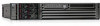
HP Integrity rx2620 Site Preparation Guide. First Edition - HP Integrity rx262 - Page 21
Computer Safety Ground, Dual Power Source Grounding, Cabinet Performance Grounding High Frequency
 |
View all HP Integrity rx2620 manuals
Add to My Manuals
Save this manual to your list of manuals |
Page 21 highlights
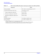
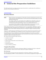
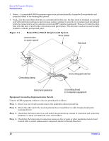
General Site Preparation Guidelines Electrical Factors NOTE The green wire ground conductor mentioned above may be a black wire marked with green tape (LAHJ). Computer Safety Ground Ground all computer equipment with the green (green/yellow) wire included in the branch circuitry. The green (green/yellow) wire ground conductors should be connected to the appropriate power panel and should be sized per applicable codes (based on circuit over current device ratings). Dual Power Source Grounding When dual power sources are utilized, strong consideration should be given to measure voltage potentials. The use of dual power might create an electrical potential that can be hazardous to personnel and might cause performance issues for the equipment. Dual power sources might originate from two different transformers or two different UPS devices. Voltage potentials from ground pin to ground pin of these sources should be measured and verified to be at or near 0.0 volts. Voltage levels that deviate or are measured above 3.0 volts should be further investigated. Increased voltages might be hazardous to personnel, and should be further investigated. Cabinet Performance Grounding (High Frequency Ground) Signal interconnects between system cabinets require high frequency ground return paths. Connect all cabinets to site ground. NOTE In some cases power distribution system green (green/yellow) wire ground conductors are too long and inductive to provide adequate high frequency ground return paths. Therefore, a ground strap (customer-supplied) should be used for connecting the system cabinet to the site grounding grid (customer-supplied). When connecting this ground, ensure that the raised floor is properly grounded for high frequency. Power panels located in close proximity to the computer equipment should also be connected to the site grounding grid. Methods of providing a sufficiently high frequency ground grid are described in the next sections. Raised Floor "High Frequency Noise" Grounding If a raised floor system is used, install a complete signal grounding grid for maintaining equal potential over a broad band of frequencies. The grounding grid should be connected to the equipment cabinet and electrical service entrance ground at multiple connection points using a minimum #6 AWG (16mm2) wire ground conductor. The following figure illustrates a metallic strip grounding system. NOTE Regardless of the grounding connection method used, the raised floor should be grounded as an absolute safety minimum. HP recommends the following approaches: • Excellent-Add a grounding grid to the subfloor. The grounding grid should be made of copper strips mounted to the subfloor. The strips should be 0.032 in. (0.08 cm) thick and a minimum of 3.0 in. (8.0 cm) wide. Connect each pedestal to four strips using 1/4 in. (6.0 mm) bolts tightened to the manufacturer's torque recommendation. Chapter 2 21
-
 1
1 -
2
-
3
-
4
-
5
-
6
-
7
-
8
-
9
-
10
-
11
-
12
-
13
-
14
-
15
-
 16
16 -
 17
17 -
 18
18 -
 19
19 -
 20
20 -
 21
21 -
 22
22 -
 23
23 -
 24
24 -
 25
25 -
 26
26 -
27
-
28
-
29
-
30
-
31
-
32
-
33
-
34
-
35
-
36
-
37
-
38
-
39
-
40
-
41
-
42
-
43
 |
 |
