HP Kayak XU 04xx HP Kayak XU Series 04xx, HP MaxiLife Hardware Monitoring - Page 7
Table 1, Basic Pre-boot Diagnostics, Error Code, Action to Take
 |
View all HP Kayak XU 04xx manuals
Add to My Manuals
Save this manual to your list of manuals |
Page 7 highlights
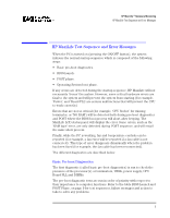
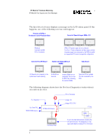
HP MaxiLife® Hardware Monitoring HP MaxiLife Test Sequence and Error Messages Table 1 The following table shows the test sequence carried out, the type of error message, and the action to take. Basic Pre-boot Diagnostics Test Error Code Action to Take Presence of a processor in the BOOT PROC [1] processor slot. This is test is for a single processor system only. Presence of either CPU or Terminator in the processor slot. Number of installed DIMMs NO CPU 1 CPU SOCKET NO RAM Control of some voltages: VRMs, 12V POWER SUPPLY Test of the correct power signals to the CPU. POWER The power supply may be OK, whereas the VRM is not. Presence of VRMs and their associated processor. POWER CPU Presence of a VRM in VRM socket 2. This test is POWER CACHE for both single and dual processor systems. Check the system board clock generators (PLL). BOARD PLL Compatibility of DIMMs. The BIOS checks that the inserted DIMMs are both compatible with one another, and compatible with the Front Side Bus frequency. RAM TYPE • Check that the processor is correctly installed in the BOOT PROC [1] slot. • Check CPUs and Terminator and VRM of installed processor. • Check that the memory module is correctly installed in the memory socket. • Check the power supply connectors, VRM, CPU. In a single processor system, check that the VRM is not plugged into the terminator socket. The error message could also show: Power CPU1 and Power CPU2. • Check that the VRM, processor and terminator are correctly installed. • Check that the VRM is not plugged on a socket with a terminator (this could be the likely cause). • Check or replace the VRM. • Check the power supply unit connectors. • Check that the VRMs are correctly installed in their VRM sockets. POWER CPU 1 - Check VRMs sockets 1 and 2. POWER CPU 2 - Check VRM socket 3. POWER CACHE - Check VRM socket 2. • Check that the VRM is correctly installed in VRM socket 2. • Check the power supply connector. • Replace the system board (PLL clock generator). • Check the installed memory modules. This error occurs when mixing incompatible memory modules, or when mixing Unbuffered and Registered memory modules. 7
-
 1
1 -
 2
2 -
 3
3 -
 4
4 -
 5
5 -
 6
6 -
 7
7 -
 8
8 -
 9
9 -
 10
10 -
 11
11 -
 12
12 -
13
-
14
-
15
-
16
-
17
-
18
-
19
-
20
-
21
-
22
-
23
-
24
-
25
-
26
-
27
-
28
 |
 |
