HP LTE Notebook PC 5100 LTE 5000 Family of Personal Computers Maintenance and
HP LTE Notebook PC 5100 Manual
 |
View all HP LTE Notebook PC 5100 manuals
Add to My Manuals
Save this manual to your list of manuals |
HP LTE Notebook PC 5100 manual content summary:
- HP LTE Notebook PC 5100 | LTE 5000 Family of Personal Computers Maintenance and - Page 1
mentioned herein may be trademarks and/or registered trademarks of their respective companies. MAINTENANCE AND SERVICE GUIDE COMPAQ LTE 5000 FAMILY OF PERSONAL COMPUTERS First Edition (September 1995) Second Edition (November 1996) Documentation Part Number 213583-002 Spare Part Number 213622-002 - HP LTE Notebook PC 5100 | LTE 5000 Family of Personal Computers Maintenance and - Page 2
and Models The Compaq LTE 5000 Family of Personal Computers introduces a new generation of performance notebook computers with advanced modularity, Pentium processors with 64-bit architecture, PCI local bus graphics, and extensive multimedia support. This full- function family of notebook computers - HP LTE Notebook PC 5100 | LTE 5000 Family of Personal Computers Maintenance and - Page 3
Compaq LTE 5000 Family of Personal Computers Models Model Processor Display Hard Drive CD-ROM Drive LTE 5000 Model Pentium/75 10.4-inch 510 MB Optional 510 CSTN CSTN/VGA LTE 5000 Model Pentium/75 11.3-Inch 810 MB Optional 810 CSTN CSTN/SVGA LTE 5000 Model Pentium - HP LTE Notebook PC 5100 | LTE 5000 Family of Personal Computers Maintenance and - Page 4
x 768 LTE 5400 Model Pentium/150 12.1-inch 2.16 GB Yes 2160 CTFT CTFT SVGA 800 x 600 1.1.3 Preinstalled Software The computer can have GD-754x Video Driver o TEAC CD-40E CD-ROM Driver and CD Audio Player for DOS o ESS Audio Driver and Audio Clip Library o Compaq Sound System Version - HP LTE Notebook PC 5100 | LTE 5000 Family of Personal Computers Maintenance and - Page 5
-To-Disk Utility 2.20.00 (0VMAKFIL.EXE) o Microsoft Infrared Monitor and Direct Cable Connect o SAFETY & COMFORT GUIDE o COMPAQ DICTIONARY o COMPAQ ONLINE USER'S GUIDE o ONLINE OPTIONS CATALOG 1.1.4 Intelligent Manageability Intelligent Manageability combines innovative hardware technology with PC - HP LTE Notebook PC 5100 | LTE 5000 Family of Personal Computers Maintenance and - Page 6
Insight Personal Edition displays a pop-up message to notify you when a hard drive or system temperature fault is detected. If the computer is connected to a network managed by Compaq Insight Manager, fault notices are also sent to the network management application. Security Management The security - HP LTE Notebook PC 5100 | LTE 5000 Family of Personal Computers Maintenance and - Page 7
three MultiBay devices simultaneously o Overall system support for up to four hard drives or two diskette drives o Up to three CD-ROM drives installed as follows: - Three CD-ROM drives: The two in the expansion base must be used for data; the CD-ROM drive in the computer can then be used for audio - HP LTE Notebook PC 5100 | LTE 5000 Family of Personal Computers Maintenance and - Page 8
base, they must be for data only. - One CD-ROM drive: It can be either data or audio and in either the computer or expansion base. o Two Type III PC Card slots o Overall system support for up to four PC cards o Charging of up to four battery packs The MultiBay ISA Expansion Base provides the same - HP LTE Notebook PC 5100 | LTE 5000 Family of Personal Computers Maintenance and - Page 9
screw installed adjacent to the hard drive release on the bottom of the computer. See Appendix C for information on using Compaq LTE Elite hard dives in the computer. 1.2.4 CD-ROM Drive The modular, 2x, 4x, and 6x CD-ROM drives are available from Compaq as a standard model or an option for the - HP LTE Notebook PC 5100 | LTE 5000 Family of Personal Computers Maintenance and - Page 10
options for the computer are also available from Compaq: o AC Adapter o Automobile Adapter o NiMH Battery Pack o Battery Fastcharger o Enhanced III External Keyboard o Compaq Mouse o Carrying Case o MultiBay Device Carrying Case o MultiBay Hard Drive Adapter AC Adapter The AC Adapter supplies DC - HP LTE Notebook PC 5100 | LTE 5000 Family of Personal Computers Maintenance and - Page 11
of two batteries in 3 hours It requires the AC Adapter or Automobile Adapter for power. Chapter 1.3 Computer External Components The external components on the front and right sides of the computer are shown in Figure 1-2 and are described in Table 1-3. Table 1-3. Computer Components - Front - HP LTE Notebook PC 5100 | LTE 5000 Family of Personal Computers Maintenance and - Page 12
QuickLock/QuickBlank. Power Management is turned on. Run Computer Setup to view or change Power Management settings. A diskette drive in the MultiBay is being accessed. A hard drive in the dedicated hard drive bay or a hard drive or CD-ROM drive in the MultiBay is being accessed. An external - HP LTE Notebook PC 5100 | LTE 5000 Family of Personal Computers Maintenance and - Page 13
- HP LTE Notebook PC 5100 | LTE 5000 Family of Personal Computers Maintenance and - Page 14
compartment for the main battery pack. 16 Hard drive bay Dedicated hard drive bay. 17 MultiBay Bay that supports multiple devices: CD-ROM drive, hard drive, battery pack, or diskette drive. The external components on the rear and left sides of the computer are shown in Figure - HP LTE Notebook PC 5100 | LTE 5000 Family of Personal Computers Maintenance and - Page 15
computer. 2 Serial connector Connects optional serial devices. 3 Parallel connector Connects optional parallel devices. 4 External options Connects the expansion base or the connector optional Automobile Adapter the AC Adapter or the optional Automobile Adapter. 7 - HP LTE Notebook PC 5100 | LTE 5000 Family of Personal Computers Maintenance and - Page 16
docking scenario when the computer is being docked. Also serves as a guide for the MPEG Adapter. 11 Mono microphone jack mass storage device bays, and battery bay. The main components of the system unit include the following: o Processor (Intel Mobile Pentium 75 MHz, 90MHz, 100MHz, 120MHz, - HP LTE Notebook PC 5100 | LTE 5000 Family of Personal Computers Maintenance and - Page 17
components: o Display assembly o Display bezel with speakers o Release latches o Brightness control actuator o Contrast control actuator (CSTN models only) o Clutch assemblies o Compaq logo Display Assembly The display assembly is replaced as a complete unit that includes: o LCD panel o LCD inverter - HP LTE Notebook PC 5100 | LTE 5000 Family of Personal Computers Maintenance and - Page 18
8-pin connector on the processor board. The LCD cable these instructions be followed when replacement of any part booting up. NOTE: Use Fn+F4 hotkeys to switch between external, internal, and simultaneous display. (The CSTN 800 x 600 does not support system board. The CPU cover is easily removed from - HP LTE Notebook PC 5100 | LTE 5000 Family of Personal Computers Maintenance and - Page 19
Compaq Logo The Compaq logo is installed on the back of the display unit. The location for the logo is indicated by an ellipse embossed in the cover. The logo is an adhesive-backed label that is available as a field replaceable unit. The label indicates which processor is installed in the computer - HP LTE Notebook PC 5100 | LTE 5000 Family of Personal Computers Maintenance and - Page 20
the following field replaceable units: o CPU cover o Internal microphone o Status panel o Processor board o Power board o Cooling fan o System board o Memory expansion board (optional) o Keyboard assembly o Auxiliary battery o Miscellaneous plastic parts CPU Cover The CPU cover is located above the - HP LTE Notebook PC 5100 | LTE 5000 Family of Personal Computers Maintenance and - Page 21
cache o System RAM o System memory expansion connector o Power, display, and standby switches o Infrared serial port (IrDA) o Display panel configuration jumpers o Power-on password jumper The computer supports 75, 90, 100, 120, 133-, and 150-MHz Mobile Pentium processors. The processor is soldered - HP LTE Notebook PC 5100 | LTE 5000 Family of Personal Computers Maintenance and - Page 22
the computer on. memory processor board. Use Table 1-5 to determine proper jumper settings for the display. Table 1-5. Display Configuration Jumpers Display Type Jumper JP3 Jumper JP2 Jumper JP4 LTE 5000 10.4 in VGA CSTN 1-2 2-3 1-2 LTE 5000 10.4 in VGA CTFT 2-3 2-3 1-2 LTE 5000 - HP LTE Notebook PC 5100 | LTE 5000 Family of Personal Computers Maintenance and - Page 23
CPU cover, EMI shield, keyboard, and display unit. The processor board is secured in place with two screws and is connected to the system board with two connectors. System Board There are three system boards for the computer: one to support the 75 MHz, 90 MHz and 120 MHz processors (LTE 5000, LTE - HP LTE Notebook PC 5100 | LTE 5000 Family of Personal Computers Maintenance and - Page 24
as determined by the user in Computer Setup. The system supports Energy Star monitors and allows the feature to be turned on/off from Computer Setup. The computer supports an interface to an MPEG and TV Video Adapter that attaches to the rear of the computer. The adapter provides up to 30 fps - HP LTE Notebook PC 5100 | LTE 5000 Family of Personal Computers Maintenance and - Page 25
5-V cards and all current Compaq PC Cards. A second PC Card controller is located in both expansion bases. The diskette drive controller supports 720K, 1.2 MB, and 1.44 MB densities as well as automatic media detection. Diskette drives can be used in the computer MultiBay and the expansion bases - HP LTE Notebook PC 5100 | LTE 5000 Family of Personal Computers Maintenance and - Page 26
integral part of the system board. In addition to the I/O panel, the system board supports the following: o PC card rails and connectors o Battery bay contacts o Hard drive bay connector o MultiBay mass storage device connector o MultiBay battery contacts o Power board connectors o Processor board - HP LTE Notebook PC 5100 | LTE 5000 Family of Personal Computers Maintenance and - Page 27
+5 volts from one of the power sources (main battery pack, AC Adapter, or Automobile Adapter). The power board is provided as a field replaceable unit. To remove and replace the power board, you must first remove the CPU cover, keyboard, and processor board. The power board connects to the system - HP LTE Notebook PC 5100 | LTE 5000 Family of Personal Computers Maintenance and - Page 28
battery. The release hook spring ensures that the battery hook firmly engages the battery. The battery battery release mechanism and consists of the following parts drive or hard drive. Pushing the release actuator also causes the CD-ROM drive release bar to eject a CD-ROM drive controller supports the - HP LTE Notebook PC 5100 | LTE 5000 Family of Personal Computers Maintenance and - Page 29
, or 6x CD-ROM drive o Second hard drive o Second battery pack o 3.5-inch diskette drive NOTE: The hard drive must be mounted in the MultiBay hard drive carrier before it can be installed into the MultiBay. The computer must be turned off when inserting a drive (not the battery pack) or removing it - HP LTE Notebook PC 5100 | LTE 5000 Family of Personal Computers Maintenance and - Page 30
new audio bass ports on both sides of the expansion base for Compaq PremierSound audio system (MultiBay ISA Expansion Base) Chapter 1.6 MultiBay Front and Right Sides Item Description 1 Monitor support cover slots 2 External options connector 3 Stereo speakers (MultiBay Expansion - HP LTE Notebook PC 5100 | LTE 5000 Family of Personal Computers Maintenance and - Page 31
ISA Expansion Base model) 8 PC Card slots 9 ISA slot access door (MultiBay ISA Expansion Base model) 10 Stereo speaker (MultiBay ISA Expansion Base model) 11 Security cable slot 12 Docking lever 13 Audio bass port (MultiBay ISA Expansion Base model) 14 Battery lights 15 Docking - HP LTE Notebook PC 5100 | LTE 5000 Family of Personal Computers Maintenance and - Page 32
4 Stereo speakers (MultiBay Expansion Base model) 5 Alignment guide 6 Power light 7 Power button 8 Infrared port 9 MultiBay drive lights 10 Audio bass port (MultiBay ISA Expansion Base model) 11 Stereo speaker (MultiBay ISA Expansion Base model) 12 Ventilation exhaust (MultiBay ISA - HP LTE Notebook PC 5100 | LTE 5000 Family of Personal Computers Maintenance and - Page 33
13 AC power connector The external components on the rear panel of the expansion base are shown in Figure 1-6 and described in Table 1-9. Table 1-9. Expansion Base Components - - HP LTE Notebook PC 5100 | LTE 5000 Family of Personal Computers Maintenance and - Page 34
o IrDA interface o Activity lights o MultiBays with ejectors o PC Card slots o ISA expansion board slot (MultiBay ISA Expansion Base model) o Computer docking mechanism 1.7.1 Main Board The expansion base main board supports the following major components: o Ethernet controller (National DP83907 - HP LTE Notebook PC 5100 | LTE 5000 Family of Personal Computers Maintenance and - Page 35
power supply is an AC-to-DC converter that serves the same function as the AC adapter and DC-to-DC converter in the computer. It provides regulated corner of the expansion base and shares a small PCB with the removable drive status lights. The board is mounted to the underside of the expansion base - HP LTE Notebook PC 5100 | LTE 5000 Family of Personal Computers Maintenance and - Page 36
ROM drive in drive light computer is being accessed 3 MultiBay hard drive/CD-ROM Hard drive or CD-ROM in one of the drive light expansion base MultiBays is being accessed. 4 MultiBay diskette drive light Diskette drive in one of the expansion base MultiBays is being accessed Battery - HP LTE Notebook PC 5100 | LTE 5000 Family of Personal Computers Maintenance and - Page 37
Computer MultiBay battery Status of battery pack in computer light MultiBay 2 Computer battery light Status of battery pack in computer battery compartment 3 MultiBay II battery light Status of battery expansion base accommodate the same drives that are used by the computer and can be used - HP LTE Notebook PC 5100 | LTE 5000 Family of Personal Computers Maintenance and - Page 38
Compaq LTE Elite hard drives. 1.7.7 PC Card Slots Each expansion base has two Type III PC Card slots that function similarly to the PC card slots on the computer. Each PC Card slot on the expansion base supports one Type I, one Type II, or one Type III PC Card. The only serviceable part of the PC - HP LTE Notebook PC 5100 | LTE 5000 Family of Personal Computers Maintenance and - Page 39
for use with the Compaq LTE 5000 Family of Personal Computers. To achieve maximum MPEG functionality support, use the Compaq MPEG and TV Video Adapter option. o Due to the vast numbers of ISA expansion boards that are available, Compaq does not guarantee or support every ISA expansion board - HP LTE Notebook PC 5100 | LTE 5000 Family of Personal Computers Maintenance and - Page 40
problem is resolved, do not complete the remaining recommended actions. o Refer to Chapter 5 for any removal and replacement procedures that are recommended. Chapter 2.1 Preliminary Steps IMPORTANT: Use the AC adapter when running POST, Computer Setup, or Computer Checkup. A low battery condition - HP LTE Notebook PC 5100 | LTE 5000 Family of Personal Computers Maintenance and - Page 41
the displayed instructions. Refer to Chapter 3 for description and spare part number for the loopback plugs. 7. Ensure that the primary hard drive is installed in the computer. 8. Ensure that the battery pack is installed in the computer and the AC Adapter is connected to the computer and plugged - HP LTE Notebook PC 5100 | LTE 5000 Family of Personal Computers Maintenance and - Page 42
current system configuration and allows you to set system and power management parameters. These parameters are stored in CMOS, and a backup copy is saved in a parameter block in system flash ROM. You can access Computer Setup by pressing F10 when the prompt appears after you turn on or restart the - HP LTE Notebook PC 5100 | LTE 5000 Family of Personal Computers Maintenance and - Page 43
drive boot disable o NTSC/PAL o Windows 95 Power Properties o Lid closure notification o Advanced LPT mode Computer Setup automatically recognizes and configures the system for new Compaq devices. It does this without prompting you for information about the devices. However, if you add a memory - HP LTE Notebook PC 5100 | LTE 5000 Family of Personal Computers Maintenance and - Page 44
the POST memory tests, numlock on or off, the drive boot sequence, boot display, and lid closure notification. NOTE: The boot sequence sets the order in which the system searches for a bootable drive to start the computer. Before changing the booting sequence, see "The Hard Drive Boot Sequence" in - HP LTE Notebook PC 5100 | LTE 5000 Family of Personal Computers Maintenance and - Page 45
PC Card slots and ring reserve feature may be enabled during Standby (Suspend). This feature is not available on the LTE 5000, LTE 5100, and LTE 5200 models. Under Power Management, you can select whether to enable Power Management while on AC or battery settings in Computer Setup and provides some additional - HP LTE Notebook PC 5100 | LTE 5000 Family of Personal Computers Maintenance and - Page 46
QuickLock/QuickBlank, power-on password from Standby, diskette drives, ports, and PC Card slots. Setup Password Use the Setup password to your setup password, you cannot change the system configuration until the computer memory is cleared of the password. CAUTION Record your setup password and - HP LTE Notebook PC 5100 | LTE 5000 Family of Personal Computers Maintenance and - Page 47
forget your power-on password, you cannot use the computer until the computer memory is cleared of the password QuickLock/QuickBlank Enabling QuickLock/QuickBlank Serial and infrared ports o Parallel port o PC Card slots o Diskette drive Disabling these devices prevents the unauthorized transfer of - HP LTE Notebook PC 5100 | LTE 5000 Family of Personal Computers Maintenance and - Page 48
has been corrupted and SCU needs to be reinitialized by running Computer Setup. CMOS failure, run SCU CMOS RAM has lost power and needs to be reinitialized by running Computer Setup. Floppy controller failed The diskette drive controller failed to respond to the reset command. Power - HP LTE Notebook PC 5100 | LTE 5000 Family of Personal Computers Maintenance and - Page 49
diskette. If the problem persists, you may need to replace the diskette drive. Floppy information invalid, The drive parameters stored in CMOS RAM do run SCU not match the diskette drives detected in the system. Hard disk controller error The hard drive controller failed to respond - HP LTE Notebook PC 5100 | LTE 5000 Family of Personal Computers Maintenance and - Page 50
value at F000:FFFF. RAM error at location RAM error occurred during memory test. None xxxx Parity Replace system board. 3 S-S-S-P-L-S-S-P The CMOS RAM test Replace system board. failed. adapter is Replace system board. faulty. 8 S-S-L-P-S-S-L-P Internal RAM is Replace processor - HP LTE Notebook PC 5100 | LTE 5000 Family of Personal Computers Maintenance and - Page 51
low battery condition could interrupt the program.) 2. Turn on the external devices that you want to test. Connect the printer if you want to print a log of error messages. 3. Insert the Compaq Diagnostics diskette in drive A. 4. Turn on or restart the computer. The computer starts from drive A, and - HP LTE Notebook PC 5100 | LTE 5000 Family of Personal Computers Maintenance and - Page 52
, or choose to print or save a log of errors. 10. Follow the instructions on the screen as the devices are tested. When testing is complete, the Test . 2. Insert the Compaq Diagnostics diskette in drive A. 3. Turn on or restart the computer. The computer starts from drive A, and the Diagnostics - HP LTE Notebook PC 5100 | LTE 5000 Family of Personal Computers Maintenance and - Page 53
7. Follow the instructions on the screen to cycle through the screens, to return to the list and choose another item, or to print the information. Chapter 2.6 Diagnostic Error Codes Diagnostic error codes occur if the system recognizes a problem while running the Compaq Diagnostic program. These - HP LTE Notebook PC 5100 | LTE 5000 Family of Personal Computers Maintenance and - Page 54
Address test failed Random pattern test failed 1. Remove the memory module and retest. 2. Install a new memory module and retest. 214 - xx Noise test failed Test 1. Check the keyboard connection. If disconnected, turn off the computer and connect the keyboard. 2. Replace the keyboard and retest. - HP LTE Notebook PC 5100 | LTE 5000 Family of Personal Computers Maintenance and - Page 55
test failed 1. Replace the diskette media and retest. 2. Check and/or replace the diskette power and signal cables and retest. 3. Replace the diskette drive and retest. 4. Replace the system board and retest. 604 - xx Diskette random read test failed 605 - xx Diskette ID media failed 606 - xx - HP LTE Notebook PC 5100 | LTE 5000 Family of Personal Computers Maintenance and - Page 56
test failed 1706 - xx Hard drive ready test failed 1707 - xx Hard drive recalibration test failed 1708 - xx Hard drive format bad track test failed 1709 - xx Hard drive reset controller test failed 1710 - xx Hard drive park head test failed 1715 - xx Hard drive head select test failed - HP LTE Notebook PC 5100 | LTE 5000 Family of Personal Computers Maintenance and - Page 57
and test with internal LCD display. 2. Check display jumpers on the processor board (see Chapter 5) 3. Replace the display assembly and retest. failed 510 - xx Video 640 x 200 mode test failed 511 - xx Video screen memory page test failed 512 - xx Video gray scale test failed 514 - xx Video - HP LTE Notebook PC 5100 | LTE 5000 Family of Personal Computers Maintenance and - Page 58
failed 2410 - xx Video 640 x 200 mode test failed 2411 - xx Video screen memory page test failed 2412 - xx Video gray scale test failed 2414 - xx Video white with internal LCD display. 3. Check display jumpers on the processor board (see Chapter 5.) 4. Replace the display assembly and retest - HP LTE Notebook PC 5100 | LTE 5000 Family of Personal Computers Maintenance and - Page 59
failed 2425 - xx ECG/VGC monochrome graphics mode test failed 2431 - xx 640 x 480 graphics test failure 2432 - xx 320 x 200 graphics (256 color mode) test failure 2448 - xx Advanced VGA Controller test failed 2451 - xx 132-column Advanced VGA test failed 2456 - xx Advanced VGA 256 Color - HP LTE Notebook PC 5100 | LTE 5000 Family of Personal Computers Maintenance and - Page 60
on the screen. The following pages contain troubleshooting information on: o Audio o Memory o Battery/battery gauge o MultiBay ISA Expansion Base o CD-ROM drive o PC Card o Diskette/diskette drive o Pointing device o Hard drive o Power o Hardware installation o Printer o Infrared connection - HP LTE Notebook PC 5100 | LTE 5000 Family of Personal Computers Maintenance and - Page 61
have been turned Run Computer Setup and off. turn on beeps. Loss of audio Moving hard drives between Download appropriate different LTE 5000 models driver from Compaq. Solving Battery and Battery Gauge Problems Some common causes and solutions for battery problems are listed in the - HP LTE Notebook PC 5100 | LTE 5000 Family of Personal Computers Maintenance and - Page 62
on the low battery indicate low battery warning beeps. condition, but computer does not beep. Volume is turned off or Press Fn+F5 to turn the turned down too low. speaker on and then adjust the volume. Problem Probable Cause Solution(s) Battery light Battery pack is already - HP LTE Notebook PC 5100 | LTE 5000 Family of Personal Computers Maintenance and - Page 63
computer (AC or battery), time you turn on battery is at end of its which charges the the computer. life. auxiliary battery. Replace the auxiliary battery. Battery charge does Battery is being exposed Keep the battery Computer Setup. An external device or PC Card is draining the battery - HP LTE Notebook PC 5100 | LTE 5000 Family of Personal Computers Maintenance and - Page 64
2-18. Solving Diskette and Diskette Drive Problems Problem Probable Cause Solution(s) Diskette drive icon Diskette drive is not Remove the diskette drive does not turn on. installed properly. and install it properly. Cannot access Real mode device drivers Remove the check marks - HP LTE Notebook PC 5100 | LTE 5000 Family of Personal Computers Maintenance and - Page 65
sector. Copy files to hard drive or another diskette. Reformat bad floppy. Drive error has occurred. Run Computer Checkup from the Compaq Diagnostics diskette. Diskette is not Format the diskette. At formatted. the system prompt, enter FORMAT A: Cannot boot from Bootable diskette is - HP LTE Notebook PC 5100 | LTE 5000 Family of Personal Computers Maintenance and - Page 66
. Hard drive error Hard drive has bad Run Computer Checkup from occurs. sectors or has failed. the Compaq Diagnostics diskette. See POST error messages. Errors occur after Additional hard drive Boot from the original booting from an does not have the LTE LTE 5000 hard drive or - HP LTE Notebook PC 5100 | LTE 5000 Family of Personal Computers Maintenance and - Page 67
hold release button on the bottom of button while removing the computer has not been hard drive from the bay. pressed. Solving Hardware Installation Problems Some common causes and solutions for hardware installation problems are listed in the following table. Table 2-20. Solving Hardware - HP LTE Notebook PC 5100 | LTE 5000 Family of Personal Computers Maintenance and - Page 68
to the numeric keypad from the and Num Lock computer. computer. function is on. Keyboard is locked. You initiated QuickLock. Enter your password to exit QuickLock. Solving Memory Problems Some common causes and solutions for memory problems are listed in the following table. - HP LTE Notebook PC 5100 | LTE 5000 Family of Personal Computers Maintenance and - Page 69
in the Using the ROM by recognized by the computer may be below downloading the current LTE 5000 in the revision 4.02 (6/13/96) ROMPaq diskette. MultiBay ISA Expansion Base. Solving PC Card Problems Some common causes and solutions for PC Card problems are listed in the following table. - HP LTE Notebook PC 5100 | LTE 5000 Family of Personal Computers Maintenance and - Page 70
slots. Card or card driver is Contact your Compaq not supported. authorized service provider for a list of PC Cards tested successfully in Compaq PC Card platforms. The PC Card drivers The PC Card slot is Run Computer Setup and (Socket Services, disabled. select the Security menu - HP LTE Notebook PC 5100 | LTE 5000 Family of Personal Computers Maintenance and - Page 71
trying to access the hard drive card using the wrong drive letter. Double-click My Computer to verify the drive letter assigned to the card. The card is not Contact your Compaq supported. authorized service provider for a list of PC Card cards tested successfully in Compaq PC Card platforms - HP LTE Notebook PC 5100 | LTE 5000 Family of Personal Computers Maintenance and - Page 72
in the following table. Also see "Solving Battery and Battery Gauge Problems" in this chapter. Table 2-27. Solving Power Problems Problem Probable Cause Solution(s) Computer won't turn Computer is not Insert battery or connect on and battery pack connected to a power an external - HP LTE Notebook PC 5100 | LTE 5000 Family of Personal Computers Maintenance and - Page 73
it was docked in automatically when expansion base. the computer reaches certain temperatures. This is normal. Fan may be blocked, Make sure airflow vents causing temperature to are not obstructed. If exceed limits. problem persists, contact your Compaq authorized service provider. - HP LTE Notebook PC 5100 | LTE 5000 Family of Personal Computers Maintenance and - Page 74
5 Volt output CN2 1, 2, 3, 4 18 Volt input from AC Adapter 5, 6, 7, 8, 9, 10 GND 11, 12, 13, 14 11 - 17 Volt battery input 15 Standby (low when computer is in standby) 16 Not used Solving Printer Problems If you experience problems printing, run a printer self-test. Refer to the - HP LTE Notebook PC 5100 | LTE 5000 Family of Personal Computers Maintenance and - Page 75
This section lists some common causes and solutions for computer display and external monitor problems. IMPORTANT: Verify that the display jumpers on the processor board are set properly for the display before proceeding with any troubleshooting. You can perform a monitor self-test on an external - HP LTE Notebook PC 5100 | LTE 5000 Family of Personal Computers Maintenance and - Page 76
external the computer screen. monitor displays information. Distorted or The ANSI.SYS driver is Add the ANSI.SYS driver garbled characters on on-pixels, often appear action is required. the computer TFT on TFT screens. Compaq display. limits the number of these on-pixels to 0.003 - HP LTE Notebook PC 5100 | LTE 5000 Family of Personal Computers Maintenance and - Page 77
-quality image, the screen in DOS mode. If computer display 800 x 600 models do not this doesn't work, does not fill the stretch the download the latest ROM screen. lower-resolution image and video drivers from of MS-DOS mode to fill Compaq. the screen. This is inherent to display panel - HP LTE Notebook PC 5100 | LTE 5000 Family of Personal Computers Maintenance and - Page 78
Chapter 3. Illustrated Parts Catalog Chapter 3.0 Introduction This chapter provides an illustrated parts breakdown and a reference for spare part numbers for the Compaq LTE 5000 Family of Personal Computers, MultiBay Expansion Base, and MultiBay ISA Expansion Base. Chapter 3.1 Computer System Major - HP LTE Notebook PC 5100 | LTE 5000 Family of Personal Computers Maintenance and - Page 79
- HP LTE Notebook PC 5100 | LTE 5000 Family of Personal Computers Maintenance and - Page 80
Table 3-1. Spare Parts - Computer System Major Components Item Description Spare Part Number 1 Display assembly, VGA, CTFT, 10.4-inch (26.4 cm). Use with Model LTE 5000 VGA (NOTE 1) 213547-001 1 Display assembly, VGA, CSTN, 10.4-inch (26.4 cm). Use with Model LTE 5000 VGA ( - HP LTE Notebook PC 5100 | LTE 5000 Family of Personal Computers Maintenance and - Page 81
X01 (NOTE 4) 6 LTE 5000 75 Mhz Processor Board 213556-001 6 LTE 5100 90 MHz Processor Board 213557-001 6 LTE 5150 100 MHz Processor Board 224136-001 6 LTE 5200 120 MHz Processor Board 213628-001 6 LTE 5250 120 MHz Processor Board 224137-001 6 LTE 5280 120 MHz - HP LTE Notebook PC 5100 | LTE 5000 Family of Personal Computers Maintenance and - Page 82
number lower than J605xxxxxxxx) are supported by Spare Part Number 213548-001. LTE 5100 and LTE 5200 units that shipped with the enhanced display (serial number J605xxxxxxxx or higher) are supported by Spare Part Number 224149-001. (Refer to Service Advisory 973 for more information) 4: Replace - HP LTE Notebook PC 5100 | LTE 5000 Family of Personal Computers Maintenance and - Page 83
- HP LTE Notebook PC 5100 | LTE 5000 Family of Personal Computers Maintenance and - Page 84
panel and cover (Shown for See Section 3.1 reference; available only as part of Display Assembly) 4 Latches Kit (SPS number 213568-001) See Section a. Clutch bracket, right b. Clutch, right c. Clutch, left d. Clutch bracket, left Chapter 3.3 Computer Base Assembly Components - HP LTE Notebook PC 5100 | LTE 5000 Family of Personal Computers Maintenance and - Page 85
- HP LTE Notebook PC 5100 | LTE 5000 Family of Personal Computers Maintenance and - Page 86
Spare Parts - Computer Base Assembly Components Item Description Spare Part Number 1 Doors and Miscellaneous Plastic Kit See Section 3.6 (SPS number 213567-001) components: a. Connector cover b. Memory slot panel with handle c. PC Card door d. Foot (Quantity = 10) e. Hard drive - HP LTE Notebook PC 5100 | LTE 5000 Family of Personal Computers Maintenance and - Page 87
- HP LTE Notebook PC 5100 | LTE 5000 Family of Personal Computers Maintenance and - Page 88
) c. Release spring (Quantity = 2) d. MultiBay device release actuator e. Battery release actuator f. Battery release holder assembly (includes release hook and leaf spring) 3 Keyboard base (available only as part of See Section 3.1 keyboard assembly) 4 EasyPoint II controller - HP LTE Notebook PC 5100 | LTE 5000 Family of Personal Computers Maintenance and - Page 89
- HP LTE Notebook PC 5100 | LTE 5000 Family of Personal Computers Maintenance and - Page 90
- Latches Kit Description Spare Part Number Latches Kit. Contains the following: 213568-001 1. Hard drive release spring 2. Battery release actuator 3. MultiBay device release actuator 4. Hard drive release button 5. Hard drive latch 6. CD-ROM release bar 7. Latch hook, left 8. Latch - HP LTE Notebook PC 5100 | LTE 5000 Family of Personal Computers Maintenance and - Page 91
- HP LTE Notebook PC 5100 | LTE 5000 Family of Personal Computers Maintenance and - Page 92
Part Number Doors and Miscellaneous Plastics Kit. 213567-001 Contains the following: 1. Hard drive door 2. Connector cover 3. PC Card door 4. Memory . Battery charger door (Quantity = 2) 18. Battery charger door spring (Quantity = 2) 19. Auxiliary battery door Chapter 3.7 Computer Optional - HP LTE Notebook PC 5100 | LTE 5000 Family of Personal Computers Maintenance and - Page 93
Parts - Computer Optional Components Item Description Spare Part Number 1 510 MB hard drive 213558-001 1 810 MB hard drive 213559-001 1 1.35 GB hard drive 213722-001 1 2.16 GB hard drive without DFP 242114-001 1 2.16 GB hard drive with DFP 242169-001 2 Diskette drive - HP LTE Notebook PC 5100 | LTE 5000 Family of Personal Computers Maintenance and - Page 94
Table 3-8. Spare Parts - Computer Standard Accessories Item Description Spare Part Number 1 Hard drive carrying case 149783-001 2 MultiBay device carrying case 213611-001 3 EasyPoint II pointing device cap (Quantity = 12) 213621-001 4 Battery pack, NiMH (Models 5000, 5100, and - HP LTE Notebook PC 5100 | LTE 5000 Family of Personal Computers Maintenance and - Page 95
(not shown) 149710-003 8 AC power cord, US (not shown) 149710-001 Chapter 3.9 Computer Optional Accessories Table 3-9. Spare Parts - Computer Optional Accessories Item Description Spare Part Number 1 Hard drive carrier 213610-001 2 Memory expansion board, 8 MB 213536-001 - HP LTE Notebook PC 5100 | LTE 5000 Family of Personal Computers Maintenance and - Page 96
Memory expansion board, 64 MB 213536-004 3 Battery Fastcharger 213614-001 4 MPEG and TV Video Adapter 213537-001 5 Automobile Adapter 194626-001 6 MPEG AC Adapter (not shown) 241909-001 Chapter 3.10 Computer Miscellaneous Spare Parts Table 3-10. Computer Miscellaneous Spare Parts - HP LTE Notebook PC 5100 | LTE 5000 Family of Personal Computers Maintenance and - Page 97
II controller to keyboard (Quantity = 2) Package: 3 Description: Standoff Drive: 3/16" Hex Quantity: 5 Where Used: Processor board to CPU base assembly (Quantity = 1) CD-ROM release bar to keyboard (Quantity = 1) Battery release holder assembly to keyboard (Quantity = 1) MultiBay - HP LTE Notebook PC 5100 | LTE 5000 Family of Personal Computers Maintenance and - Page 98
Compaq LTE 5000 Family of Personal Computers Maintenance & Service Guide 213622-001 Compaq LTE 5000 Family of Personal Computers Illustrated Parts Map (Quantity = 10) * 213677-002 Compaq LTE 5000 Family of Personal Computers Beyond Setup Guide (Brazilian/Portuguese) 213624-201 Compaq LTE 5000 - HP LTE Notebook PC 5100 | LTE 5000 Family of Personal Computers Maintenance and - Page 99
051 Compaq LTE 5000 Family of Personal Computers Online User's Guide (German) ** 213625-041 Compaq LTE 5000 Family of Personal Computers Online User's Guide (Italian) ** 213625-061 Compaq LTE 5000 Family of Personal Computers Online User's Guide (Japanese) ** 213625-291 Compaq LTE 5000 Family - HP LTE Notebook PC 5100 | LTE 5000 Family of Personal Computers Maintenance and - Page 100
The Compaq LTE 5000 Family of Personal Computers Online User's Guide is provided on 3.5-inch diskette. Chapter 3.12 Software Table 3-13. Spare Parts - Software Description Spare Part Number LTE 5000 Video Drivers Support Kit 213638-XXX LTE 5000 CD-ROM Drivers Support Kit 213639 - HP LTE Notebook PC 5100 | LTE 5000 Family of Personal Computers Maintenance and - Page 101
language code when ordering, e.g., 213638-001 for English LTE 5000 Video Drivers Support Kit * NOTE: QuickFind is updated monthly. To complete the QuickFind part number add the suffix from the table below for the desired month. If you do not specify the 3-digit suffix, the default is the current - HP LTE Notebook PC 5100 | LTE 5000 Family of Personal Computers Maintenance and - Page 102
- HP LTE Notebook PC 5100 | LTE 5000 Family of Personal Computers Maintenance and - Page 103
- MultiBay Expansion Base Cover Assemblies Item Description Spare Part Number 1 Monitor support cover with logo 213713-001 2 Top cover assembly. Includes 213711-001 EMI shield, release mechanism, doors, guides, monitor support cover slot caps with springs, labels, and logo - HP LTE Notebook PC 5100 | LTE 5000 Family of Personal Computers Maintenance and - Page 104
- HP LTE Notebook PC 5100 | LTE 5000 Family of Personal Computers Maintenance and - Page 105
ISA Expansion Base Cover Assemblies Item Description Spare Part Number 1 Monitor support cover w/logo 213713-001 2 Top cover assembly. Includes EMI shield, release mechanism, doors, guides, monitor support cover slot caps with springs, labels, and logo. 213711-003 3 Base - HP LTE Notebook PC 5100 | LTE 5000 Family of Personal Computers Maintenance and - Page 106
- HP LTE Notebook PC 5100 | LTE 5000 Family of Personal Computers Maintenance and - Page 107
Power supply with fan 213707-001 4 MultiBay assembly with ejector 213757-001 5 MultiBay connector board 213758-001 6 Speaker holder (Part of See Section 3.16 Miscellaneous Plastics Kit 213717-001) 7 Speaker 213763-001 8 Top cover assembly (See Section 3.15 for - HP LTE Notebook PC 5100 | LTE 5000 Family of Personal Computers Maintenance and - Page 108
- HP LTE Notebook PC 5100 | LTE 5000 Family of Personal Computers Maintenance and - Page 109
- MultiBay ISA Expansion Base Major Components Item Description Spare Part Number 1 MPEG connector w/frame 242128-001 2 Main I/O board 241958-001 3 Power supply w/fan 241959-001 4 MultiBay assembly w/ejector Included with Item 7 5 MultiBay connector board Included - HP LTE Notebook PC 5100 | LTE 5000 Family of Personal Computers Maintenance and - Page 110
- HP LTE Notebook PC 5100 | LTE 5000 Family of Personal Computers Maintenance and - Page 111
Cover Assembly Components Description Spare Part Number Top Cover Assembly PC Card door assembly (NOTE 2) 7. Docking mechanism handle cover (NOTE 1) 8. Docking mechanism handle shield (NOTE 1) 9. Alignment guide, right (NOTE 1) 10. Docking mechanism lever (NOTE 1) 11. Monitor support - HP LTE Notebook PC 5100 | LTE 5000 Family of Personal Computers Maintenance and - Page 112
- HP LTE Notebook PC 5100 | LTE 5000 Family of Personal Computers Maintenance and - Page 113
Plastics Kit Description Spare Part Number Miscellaneous Plastics Kit. Contains the 213717-001 following: 1. PC Card doors assembly 2. MultiBay door (Quantity = 2) 3. MultiBay door spring (Quantity = 2) 4. Monitor support cover slot caps 5. Monitor support cover slot cap spring - HP LTE Notebook PC 5100 | LTE 5000 Family of Personal Computers Maintenance and - Page 114
- HP LTE Notebook PC 5100 | LTE 5000 Family of Personal Computers Maintenance and - Page 115
Alignment guide spring (Quantity = 2) 12. Alignment guide (left) 13. Alignment guide screw (Quantity = 4 /not shown) Chapter 3.18 MultiBay and MultiBay ISA Expansion Base Miscellaneous Parts Table 3-19. Spare Parts: MultiBay Expansion Base Miscellaneous Parts Description Spare Part Number - HP LTE Notebook PC 5100 | LTE 5000 Family of Personal Computers Maintenance and - Page 116
Quantity = 3) MultiBay connector board to top cover assembly (Quantity = 3) PC card door assembly to top cover assembly (Quantity 3) IrDA board to top Quantity = 1) Computer connector bezel to top cover assembly (Quantity = 2) Description: 8TXWC25100M Nylok Screw Drive: T8/Slotted - HP LTE Notebook PC 5100 | LTE 5000 Family of Personal Computers Maintenance and - Page 117
Spare Part Number LTE 5000 MultiBay Expansion Base Installation and Operations Guide (Dutch) 213762-331 LTE 5000 MultiBay Expansion Base Installation and Operations Guide (English) 213762-001 LTE 5000 MultiBay Expansion Base Installation and Operations Guide (French) 213762-051 LTE 5000 - HP LTE Notebook PC 5100 | LTE 5000 Family of Personal Computers Maintenance and - Page 118
Replacement Preliminaries Chapter 4.0 Introduction This chapter provides general service information for the computer. Adherence to the procedures and precautions described in this chapter is essential for proper service. Chapter 4.1 Electrostatic Discharge Information A sudden discharge of static - HP LTE Notebook PC 5100 | LTE 5000 Family of Personal Computers Maintenance and - Page 119
Place reusable electrostatic-sensitive parts from assemblies in protective drives and hard drives, use the following precautions: o Handle drives gently, using static-guarding techniques. o Avoid touching the connectors on the hard drive. o Store drives in the carrying case. Use the Hard Drive - HP LTE Notebook PC 5100 | LTE 5000 Family of Personal Computers Maintenance and - Page 120
protection. o Handle electrostatic sensitive components, parts, and assemblies by the case or PCM service tools, such as cutters, screwdrivers, and vacuums, that are conductive. o Use a portable field service compatible with most types of shoes or boots. On conductive floors or dissipative floor - HP LTE Notebook PC 5100 | LTE 5000 Family of Personal Computers Maintenance and - Page 121
table or floor mats with hard tie to ground o Field service kits o Static awareness labels Service Considerations Listed below are some of the considerations that you should keep in mind during the disassembly and assembly of the computer. 4.2.1 Tool and Software Requirements To service the computer - HP LTE Notebook PC 5100 | LTE 5000 Family of Personal Computers Maintenance and - Page 122
, and ensure that the cables are routed in such a way that they cannot be caught or snagged by parts being removed or replaced. CAUTION When servicing this computer, ensure that cables are placed in their proper location during the reassembly process. Improper cable placement can damage the - HP LTE Notebook PC 5100 | LTE 5000 Family of Personal Computers Maintenance and - Page 123
The computer uses a zero insertion force (ZIF) connector for the keyboard cable to the system board. cable. Never pull or twist on the cable while it is connected 4.2.4 Plastic Parts Plastic parts can be damaged by the use of excessive force during disassembly and reassembly. When handling the - HP LTE Notebook PC 5100 | LTE 5000 Family of Personal Computers Maintenance and - Page 124
Introduction This chapter presents the removal and replacement procedures for the computer. Chapter 5.1 Serial Number The computer serial number should be reported to Compaq when requesting information or ordering spare parts. The serial number is displayed immediately above the serial connector on - HP LTE Notebook PC 5100 | LTE 5000 Family of Personal Computers Maintenance and - Page 125
Chapter 5.3 Preparing the Computer for Disassembly Before beginning removal and replacement procedures, complete the following procedures: 1. Undock the computer from the expansion base (Section 5.3.1). 2. Disconnect AC power and any external devices (Section 5.3.2). - HP LTE Notebook PC 5100 | LTE 5000 Family of Personal Computers Maintenance and - Page 126
(Section 5.3.4). 5. Remove the hard drive (Section 5.3.5). 6. Remove the battery or mass storage device from the MultiBay (Section 5.3.6). 7. Remove any PC cards (section 5.3.7). NOTE: It is important that these instructions be followed when replacement of any part requires removal of the display - HP LTE Notebook PC 5100 | LTE 5000 Family of Personal Computers Maintenance and - Page 127
5.3.1 for undocking instructions. If the computer is not docked in an expansion base, see Figure 5-4 and complete the following steps to disconnect the computer: 1. Turn off [1] the computer. 2. Disconnect the AC Adapter power cord from the wall outlet [2]. 3. Disconnect the AC Adapter [3] from the - HP LTE Notebook PC 5100 | LTE 5000 Family of Personal Computers Maintenance and - Page 128
compartment. To prevent damage, do not allow metal objects to touch the battery contacts. Place only the battery pack for the Compaq LTE 5000 Personal Computer into the battery compartment. Do not force the battery pack into the bay if insertion does not occur easily. CAUTION Do not crush - HP LTE Notebook PC 5100 | LTE 5000 Family of Personal Computers Maintenance and - Page 129
on the battery pack; it will lock into place. Using the Battery Pack as a Counterweight With the display open and the mass storage devices and battery pack removed from the computer bays, the weight of the display makes the computer susceptible to being easily tipped over. When performing service - HP LTE Notebook PC 5100 | LTE 5000 Family of Personal Computers Maintenance and - Page 130
is stored in a compartment on the bottom of the computer (Figure 5-7). The auxiliary battery should be removed prior to servicing the computer. Removing the Auxiliary Battery To remove the auxiliary battery, complete the following steps: 1. Using a small flat-blade screwdriver to release the door - HP LTE Notebook PC 5100 | LTE 5000 Family of Personal Computers Maintenance and - Page 131
2. Lift the auxiliary battery out of its compartment [1] and disconnect the auxiliary battery cable [2] as shown in Figure 5-8. - HP LTE Notebook PC 5100 | LTE 5000 Family of Personal Computers Maintenance and - Page 132
is not cylindrical but protrudes along one side. When installing the auxiliary battery, this side of the battery must enter the battery compartment first. To install an auxiliary battery, complete the following steps: 1. Remove the auxiliary battery compartment door if it is not already off (Figure - HP LTE Notebook PC 5100 | LTE 5000 Family of Personal Computers Maintenance and - Page 133
Install the auxiliary battery compartment door (Figure 5-7). 5.3.5 Hard Drive The middle compartment on the front of the computer is a dedicated hard drive bay. No other device should be installed in this bay. Remove the hard drive prior to performing maintenance on the computer. IMPORTANT: Be sure - HP LTE Notebook PC 5100 | LTE 5000 Family of Personal Computers Maintenance and - Page 134
2. Open the hard drive bay door [1], and while holding the hard drive release actuated [2], pull on the tab [3] to remove the hard drive (Figure 5-11). - HP LTE Notebook PC 5100 | LTE 5000 Family of Personal Computers Maintenance and - Page 135
the hard drive bay door. 4. Install the security screw (optional) as shown in Figure 5-10. 5.3.6 MultiBay Device Either a mass storage device or a battery pack can be installed in the MultiBay. The device installed in the MultiBay should be removed prior to performing maintenance on the computer - HP LTE Notebook PC 5100 | LTE 5000 Family of Personal Computers Maintenance and - Page 136
1. Remove the MultiBay security screw (Figure 5-12). 2. Push the MultiBay device release [1] toward the front of the computer and pull the device [2] out of the MultiBay (Figure 5-13). - HP LTE Notebook PC 5100 | LTE 5000 Family of Personal Computers Maintenance and - Page 137
as shown in Figure 5-12. 5.3.7 PC Card Compaq recommends that you remove any installed PC Cards (PCMCIA) before performing any service on the computer. To remove a PC card, complete the following steps: 1. Open the PC Card door [1] (Figure 5-14). 2. Press on the PC Card release button [2] to remove - HP LTE Notebook PC 5100 | LTE 5000 Family of Personal Computers Maintenance and - Page 138
procedures that do not require access to the internal components of the computer. This includes: o Computer logo o Computer feet o Connector cover o Auxiliary battery compartment door o Memory expansion board o EasyPoint II pointing device o Hard drive bay door o PC Card door 5.4.1 Computer Logo - HP LTE Notebook PC 5100 | LTE 5000 Family of Personal Computers Maintenance and - Page 139
logo identifies the model of the computer. A logo for each model is included with the display assembly spare parts kit. The logo has an adhesive backing for installation. Select the appropriate logo for your computer model, remove the protective covering from the adhesive back, and install the - HP LTE Notebook PC 5100 | LTE 5000 Family of Personal Computers Maintenance and - Page 140
into place. To remove and replace a connector cover, complete the following steps: 1. Open the connector cover. 2. Flex the center of the cover away from the computer (Figure 5-17) until the pivots on each end of the cover disengage the pivot holes in the - HP LTE Notebook PC 5100 | LTE 5000 Family of Personal Computers Maintenance and - Page 141
install a connector cover. 5.4.4 Auxiliary Battery Compartment Door See Section 5.3.4 for instructions on how to remove and replace the auxiliary battery compartment door. 5.4.5 Memory Expansion Board The memory expansion board is installed from the outside of the computer and is located behind the - HP LTE Notebook PC 5100 | LTE 5000 Family of Personal Computers Maintenance and - Page 142
3. Pull on the handle [2] to remove the memory expansion board from the computer (Figure 5-18). Reverse the above procedure to install a memory expansion board. IMPORTANT: Run Computer Setup after installing a memory expansion board. 5.4.6 EasyPoint II Pointing Device The EasyPoint II pointing - HP LTE Notebook PC 5100 | LTE 5000 Family of Personal Computers Maintenance and - Page 143
5.4.7 Hard Drive Bay Door The hard drive bay door snaps into place. To remove the hard drive bay door, complete the following steps: 1. Position the computer on a tabletop so the front edge of the computer is just off the edge of the table (Figure 5-20). - HP LTE Notebook PC 5100 | LTE 5000 Family of Personal Computers Maintenance and - Page 144
until the door is released. To install the hard drive door, orient the door to 90 degrees from its closed position and snap it onto the pivot studs on the computer. 5.4.8 PC Card Door The PC Card door snaps into place. To remove and replace the PC Card door, complete the following steps: 1. Open the - HP LTE Notebook PC 5100 | LTE 5000 Family of Personal Computers Maintenance and - Page 145
of the door up until the pivots on each end of the door disengage the pivot holes in the computer housing (Figure 5-21). Reverse this procedure to install the PC Card door. Chapter 5.5 CPU Cover Assembly The CPU cover assembly must be removed to gain access to any of the interior components of the - HP LTE Notebook PC 5100 | LTE 5000 Family of Personal Computers Maintenance and - Page 146
Assembly To remove and replace the CPU cover assembly, complete the following steps: 1. Prepare the computer for disassembly as described in Section 5.3. 2. Remove the three screws from the back of the computer (Figure 5-22). 3. Open the display panel and tilt the display panel all the way back - HP LTE Notebook PC 5100 | LTE 5000 Family of Personal Computers Maintenance and - Page 147
cover forward and out of the computer (Figure 5-23). Reverse the above procedure to install the CPU cover assembly. IMPORTANT: A set of warning labels is included with each CPU cover assembly spare parts kit. Select a label with the language that matches the keyboard language and install the label - HP LTE Notebook PC 5100 | LTE 5000 Family of Personal Computers Maintenance and - Page 148
To install, simply snap the power switch actuator, with spring installed, into place. 5.5.3 Standby (Suspend) Button To remove the standby (suspend) button, complete the following steps: 1. Remove the CPU cover as described in Section 5.5.1. 2. From the bottom side of the CPU cover, squeeze the tabs - HP LTE Notebook PC 5100 | LTE 5000 Family of Personal Computers Maintenance and - Page 149
To install, simply snap the standby (suspend) button into place. To avoid losing the spring, this task is better performed with the CPU cover inverted. 5.5.4 Display Switch Button The display switch button is installed with a snap action. To remove, simply pull it out of its mounting hole (Figure 5- - HP LTE Notebook PC 5100 | LTE 5000 Family of Personal Computers Maintenance and - Page 150
a display switch button, snap it into place. Chapter 5.6 Microphone With the CPU cover removed, the microphone is readily accessible on the right-hand side of the computer above the keyboard. The microphone is seated in a boot that is then installed in the keyboard plastic. To remove and replace the - HP LTE Notebook PC 5100 | LTE 5000 Family of Personal Computers Maintenance and - Page 151
its boot out of the computer (Figure 5-27). NOTE: The microphone extension cable cannot be properly accessed for service until the processor board is removed. See Section 5.11 for details on the extension cable. To install a microphone, reverse the above procedure. Chapter 5.7 Status Panel The CPU - HP LTE Notebook PC 5100 | LTE 5000 Family of Personal Computers Maintenance and - Page 152
4. Remove the two status panel screws [2] (Figure 5-28). 5. Lift the status panel [3] out of the computer. Reverse the above procedure to install the status panel, taking care to route the cable properly. Chapter 5.8 Display Assembly Maintenance of the display assembly includes - HP LTE Notebook PC 5100 | LTE 5000 Family of Personal Computers Maintenance and - Page 153
the Display Assembly To remove and install the display assembly, complete the following steps: 1. Prepare the computer for disassembly as described in Section 5.3. 2. Remove the CPU cover as described in Section 5.5.1. 3. Disconnect the display cables: one connector [4] and grounding lug [5] on the - HP LTE Notebook PC 5100 | LTE 5000 Family of Personal Computers Maintenance and - Page 154
match the computer model (Section 5.4.1). NOTE: It is important that these instructions be followed when replacement of any part requires removal of hinge. Failure to properly seat the screws may prevent the unit from booting up. IMPORTANT: When installing the display, take care not to damage the - HP LTE Notebook PC 5100 | LTE 5000 Family of Personal Computers Maintenance and - Page 155
To remove the display bezel, complete the following steps: 1. Remove the display assembly as described in Section 5.8.1. 2. Remove the screw covers and screws (Figure 5-31). NOTE: The upper and lower screw covers are not the same. 3. Using a case tool, begin at the top and pry the display bezel - HP LTE Notebook PC 5100 | LTE 5000 Family of Personal Computers Maintenance and - Page 156
IMPORTANT: Note the routing of the display cables to ensure proper routing at reassembly. Reverse the above procedure to install the display bezel, taking care to properly align the brightness/contrast control(s) with their switches. 5.8.3 Removing and Installing the Latches To remove the latches, - HP LTE Notebook PC 5100 | LTE 5000 Family of Personal Computers Maintenance and - Page 157
4. Lift out the latch [2] and its attached spring (Figure 5-33). Reverse the above procedure to install a latch assembly. 5.8.4 Removing and Installing the Clutch Assembly To remove a clutch assembly, complete the following steps: 1. Remove the display assembly as described in Section 5.8.1. 2. - HP LTE Notebook PC 5100 | LTE 5000 Family of Personal Computers Maintenance and - Page 158
Reverse the above procedure to install a clutch assembly and bracket. 5.8.5 Brightness/Contrast Control Actuator To remove a brightness/contrast control actuator, complete the following steps: 1. Remove the display assembly as described in Section 5.8.1. 2. Remove the display bezel as described in - HP LTE Notebook PC 5100 | LTE 5000 Family of Personal Computers Maintenance and - Page 159
with one screw and is keyed to provide proper installation. The right clutch cradle uses no screws for installation and simply lifts out of the computer. To remove the clutch cradles, complete the following steps: 1. Remove the display assembly (Section 5.8.1). 2. Remove the left cradle screw and - HP LTE Notebook PC 5100 | LTE 5000 Family of Personal Computers Maintenance and - Page 160
of the keyboard assembly includes removal and replacement of the following: o Keyboard assembly o EasyPoint II controller o Battery eject mechanism o MultiBay device eject mechanism o Hard drive latch 5.9.1 Removing and Installing the Keyboard To remove the keyboard, complete the following steps: - HP LTE Notebook PC 5100 | LTE 5000 Family of Personal Computers Maintenance and - Page 161
1. Remove the CPU cover as described in Section 5.5.1. 2. Remove the keyboard screws (Figure 5-37). 3. Remove the screws [1] from the rear corners of the keyboard (Figure 5-38). Note that ground lugs are attached by these screws. - HP LTE Notebook PC 5100 | LTE 5000 Family of Personal Computers Maintenance and - Page 162
4. Remove the microphone [2] (Figure 5-38). You can leave it attached to its extension cable. 5. Separate the keyboard from the base and shift it slightly to gain better access to the keyboard ZIF connector [1] (Figure 5-39), then disconnect the ZIF connector. - HP LTE Notebook PC 5100 | LTE 5000 Family of Personal Computers Maintenance and - Page 163
6. Disconnect the EasyPoint II controller cable [2] from the system board (Figure 5-39). 7. Lift the keyboard out. Reverse this procedure to install the keyboard. NOTE: Be sure to connect the ground lugs at the rear of the keyboard. 5.9.2 Removing and Installing the EasyPoint II Controller To remove - HP LTE Notebook PC 5100 | LTE 5000 Family of Personal Computers Maintenance and - Page 164
3. Disconnect the cable from the ZIF connector on the EasyPoint II Controller (Figure 5-41). The ZIF connector is located on the back side of the controller board. - HP LTE Notebook PC 5100 | LTE 5000 Family of Personal Computers Maintenance and - Page 165
in their proper orientations. Reverse the above procedure to install the EasyPoint II controller. 5.9.3 Removing and Installing the Battery Release Assembly To remove the battery release assembly, complete the following steps: 1. Remove the keyboard as described in Section 5.9.1. 2. Remove the two - HP LTE Notebook PC 5100 | LTE 5000 Family of Personal Computers Maintenance and - Page 166
. Use the locating pins adjacent to each mounting hole to locate the release holder properly. NOTE: At reassembly, make certain that the spring on the battery release is not trapped between the release holder and side plastic. The spring should be below the holder (Figure 5-43). - HP LTE Notebook PC 5100 | LTE 5000 Family of Personal Computers Maintenance and - Page 167
5.9.4 Removing and Installing the MultiBay Release Assembly To remove the MultiBay release assembly, complete the following steps: 1. Remove the keyboard as described in Section 5.9.1. 2. Remove the standoff [1] from the CD-ROM eject bar [2] and lift out the eject bar (Figure 5-44). - HP LTE Notebook PC 5100 | LTE 5000 Family of Personal Computers Maintenance and - Page 168
3. Remove the standoff and screw from the release holder (Figure 5-45). - HP LTE Notebook PC 5100 | LTE 5000 Family of Personal Computers Maintenance and - Page 169
4. Lift out the release holder (Figure 5-45). The release is attached to the holder with its spring. The release holder, spring and latch are installed as an assembly. Reverse the above procedure to install the MultiBay release assembly. Use the locating pins adjacent to each mounting hole to locate - HP LTE Notebook PC 5100 | LTE 5000 Family of Personal Computers Maintenance and - Page 170
the Hard Drive Latch The hard drive latch assembly consists of the hard drive release, latch, and spring. It is held in place with one screw. To remove and replace the hard drive latch, complete the following steps: 1. Remove the keyboard as described in Section 5.9.1. 2. Remove the hard drive - HP LTE Notebook PC 5100 | LTE 5000 Family of Personal Computers Maintenance and - Page 171
air vent on the left side of the computer and is plugged into the system board. After removing the CPU cover, the fan is easily removed by disconnecting To remove the fan, complete the following steps: 1. Remove the CPU cover (Section 5.5). 2. Remove the keyboard (Section 5.9.1). 3. Disconnect the fan - HP LTE Notebook PC 5100 | LTE 5000 Family of Personal Computers Maintenance and - Page 172
oriented with the label on top and the airflow arrow pointing out of the computer. Chapter 5.11 Processor Board To remove the processor board, complete the following steps: 1. Remove the CPU cover as described in Section 5.5.1. 2. Remove the status panel as described in Section 5.6. 3. Remove - HP LTE Notebook PC 5100 | LTE 5000 Family of Personal Computers Maintenance and - Page 173
8. Disconnect the thermistor cable [1] as shown in Figure 5-50. - HP LTE Notebook PC 5100 | LTE 5000 Family of Personal Computers Maintenance and - Page 174
9. Remove the screw [2] from the right rear corner of the processor board (Figure 5-50). 10. Remove the processor board as shown in Figure 5-51. - HP LTE Notebook PC 5100 | LTE 5000 Family of Personal Computers Maintenance and - Page 175
Before installing the processor board, verify that the display jumpers are appropriately configured for the type of display installed in the computer. The jumper locations are shown in Figure 5-52, and jumper configurations are presented in Table 5-1. - HP LTE Notebook PC 5100 | LTE 5000 Family of Personal Computers Maintenance and - Page 176
Jumpers Display Type JP3 JP2 JP4 LTE 5000 10.4 in VGA CSTN 1-2 2-3 1-2 LTE 5000 10.4 in VGA CTFT 2-3 2-3 1-2 LTE 5000 11.3 in SVGA CSTN 1-2 2-3 2-3 LTE 5100 10.4 in SVGA CTFT 2-3 2-3 2-3 LTE 5150 Rev. 4.X * 11.3 in 1-2 1-2 1-2 SVGA CSTN LTE 5150 Rev. 2.X * 11.3 in - HP LTE Notebook PC 5100 | LTE 5000 Family of Personal Computers Maintenance and - Page 177
CTFT LTE 5400 12.1 in 1024x768 2-3 2-3 2-3 CTFT * Verify the display panel revision is located on the left side of the display assembly. Reverse the above procedure to install a processor board, taking care with the placement of the EMI shield (Figure 5-53). Chapter 5.12 Microphone - HP LTE Notebook PC 5100 | LTE 5000 Family of Personal Computers Maintenance and - Page 178
Chapter 5.13 Power Board To remove the power board, complete the following steps: 1. Remove the processor board as described in Section 5.11. 2. Remove the screw near the hard drive bay (Figure 5-55) and lift the power board out of the computer. - HP LTE Notebook PC 5100 | LTE 5000 Family of Personal Computers Maintenance and - Page 179
5.14 System Board To remove the system board, complete the following steps: 1. Remove the CPU panel as described in Section 5.5.1. 2. Remove the display as described in Section 5.8.1. 3. Remove the processor board as described in Section 5.11. 4. Remove the power board as described in Section - HP LTE Notebook PC 5100 | LTE 5000 Family of Personal Computers Maintenance and - Page 180
6. Remove the standoff from the left rear corner of the system board (Figure 5-57). - HP LTE Notebook PC 5100 | LTE 5000 Family of Personal Computers Maintenance and - Page 181
7. Remove the screw from the front left and the screw from the right rear of the system board (Figure 5-57). 8. Remove the two screwlocks from the option connector on the rear of the computer (Figure 5-58). - HP LTE Notebook PC 5100 | LTE 5000 Family of Personal Computers Maintenance and - Page 182
9. The system board can now be lifted out of the computer as shown in Figure 5-59. - HP LTE Notebook PC 5100 | LTE 5000 Family of Personal Computers Maintenance and - Page 183
NOTE: Begin lifting the system board at the edge near the hard drive shield. The sheet metal may have to be deflected slightly to provide clearance for removing the board. Continue lifting the system board out toward the front of the computer. Reverse the above procedure to install the system board. - HP LTE Notebook PC 5100 | LTE 5000 Family of Personal Computers Maintenance and - Page 184
the MultiBay ISA Expansion Base, refer to Section 7. Chapter 6.1 Serial Number The expansion base serial number should be reported to Compaq when requesting information or ordering spare parts. The serial number is displayed on the rear of the expansion base to the right of the serial port. Chapter - HP LTE Notebook PC 5100 | LTE 5000 Family of Personal Computers Maintenance and - Page 185
base top cover (Service Spare Part Number 213711-003). 1. Do not remove the plastic hole cover. 2. Discard the fan. Before beginning removal and replacement procedures, complete the following steps: 1. Undock the computer from the expansion base (Section 5.3.1). 2. Disconnect AC power and any - HP LTE Notebook PC 5100 | LTE 5000 Family of Personal Computers Maintenance and - Page 186
6.3.2 Disconnecting the Expansion Base 1. Turn off the expansion base and undock the computer if it is docked in the expansion base. See Section 5.3.1 for detailed instructions. 2. Disconnect the power cord from the AC source and from the expansion base. 3. Disconnect all peripheral devices from the - HP LTE Notebook PC 5100 | LTE 5000 Family of Personal Computers Maintenance and - Page 187
the battery contacts. Place only the battery pack for the Compaq LTE 5000 Personal Computer into the battery compartment. Do not force the battery pack battery components. There are no field-serviceable parts located inside the battery pack. Removing the Battery Pack To remove a battery pack - HP LTE Notebook PC 5100 | LTE 5000 Family of Personal Computers Maintenance and - Page 188
battery to the left. Installing a Battery Pack To install a battery pack into a MultiBay, complete the following steps: 1. With the label facing up and the connectors facing in, align the left side of the battery pack with the left side of the MultiBay, and push the battery the battery pack - HP LTE Notebook PC 5100 | LTE 5000 Family of Personal Computers Maintenance and - Page 189
this manual for more details CAUTION Removable drives should only be inserted in or removed from the expansion base when the computer is turned off. Failure to follow this precaution can result in damage to the drive and expansion base and cause loss or corruption of data Before a hard drive can - HP LTE Notebook PC 5100 | LTE 5000 Family of Personal Computers Maintenance and - Page 190
4. Push the latch inside the carrier to the left to secure the hard drive in place. 5. Align the left side of the carrier with the a Diskette Drive or CD-ROM Drive To install a diskette drive or CD-ROM drive into the MultiBay, complete the following steps: 1. Turn off the computer. 2. Align - HP LTE Notebook PC 5100 | LTE 5000 Family of Personal Computers Maintenance and - Page 191
the MultiBay and push the drive into the bay until it is seated. 6.3.5 PC Card All PC cards should be removed from the expansion base before performing any internal maintenance on the computer. Removing a PC Card To remove a PC Card, complete the following steps: 1. Push the PC Card release button - HP LTE Notebook PC 5100 | LTE 5000 Family of Personal Computers Maintenance and - Page 192
2. Place the PC Card in the tracks with the card connector to the inside and label up. 3. Slide the card in until it seats. The door remains open - HP LTE Notebook PC 5100 | LTE 5000 Family of Personal Computers Maintenance and - Page 193
door [2] provides visual access to the MPEG connector for guiding the connector into place when installing the bottom cover assembly with the connector attached to the bottom cover (Figure 6-8). Procedures presented later in this manual prescribe separating the MPEG connector from the bottom cover - HP LTE Notebook PC 5100 | LTE 5000 Family of Personal Computers Maintenance and - Page 194
3. Lift the bottom cover from the expansion base (Figure 6-10). - HP LTE Notebook PC 5100 | LTE 5000 Family of Personal Computers Maintenance and - Page 195
To install the bottom cover assembly, reverse the procedure presented above. Chapter 6.6 MPEG Connector The MPEG connector plugs into the main board and is accessed by removing the bottom cover assembly. Remove the bottom cover assembly as described in Section 6.5 and disconnect the MPEG connector - HP LTE Notebook PC 5100 | LTE 5000 Family of Personal Computers Maintenance and - Page 196
Reverse this procedure to install the MPEG connector. Chapter 6.7 Power Supply The power supply is mounted in the right rear corner of the expansion base when viewed with the base placed top side down on the work surface. It is replaced as an assembly with its fan. To remove the power supply, - HP LTE Notebook PC 5100 | LTE 5000 Family of Personal Computers Maintenance and - Page 197
5. Note the routing of the ground wires attached to the rear power supply screws. Remove the four screws and lift the power supply out (Figure 6-13). - HP LTE Notebook PC 5100 | LTE 5000 Family of Personal Computers Maintenance and - Page 198
remove the main board, complete the following steps: 1. Prepare the expansion base for disassembly as described in Section 6.3. 2. Remove the two shoulder screws from the computer connector as shown in Figure 6-14. - HP LTE Notebook PC 5100 | LTE 5000 Family of Personal Computers Maintenance and - Page 199
3. Remove the bottom cover as described in Section 6.5. 4. Note the routing of all cables and disconnect the power cable [1], speaker cables [2], IrDA cable [3], power supply cable [4], and cable [5] (Figure 6-15). - HP LTE Notebook PC 5100 | LTE 5000 Family of Personal Computers Maintenance and - Page 200
5. Disconnect the fan [1] and fan power [2] at the Fan Control Board (Figure 6-16). - HP LTE Notebook PC 5100 | LTE 5000 Family of Personal Computers Maintenance and - Page 201
6. Remove the remaining three screws from the main board and the two screws from the CPU connector bezel (Figure 6-17). - HP LTE Notebook PC 5100 | LTE 5000 Family of Personal Computers Maintenance and - Page 202
7. Lift the main board out of the base. Begin lifting at the front edge of the board [1] . The CPU connector bezel [2] comes off with the board but is not attached to the board. Some manipulation is required around the PC Card door module (Figure 6-18). - HP LTE Notebook PC 5100 | LTE 5000 Family of Personal Computers Maintenance and - Page 203
main board must be removed to remove and replace the CPU connector bezel. See Section 6.8 for details. Chapter 6.10 MultiBay Assembly The main board must be removed before removing a MultiBay assembly. The MultiBay assembly is spared as part of the top cover assembly. However, the Multibay assembly - HP LTE Notebook PC 5100 | LTE 5000 Family of Personal Computers Maintenance and - Page 204
2. Begin lifting at the end of the assembly toward the MultiBay Connector Board and lift the MultiBay assembly out (Figure 6-20). - HP LTE Notebook PC 5100 | LTE 5000 Family of Personal Computers Maintenance and - Page 205
Reverse the above procedure to install a MultiBay assembly, inserting the end nearest the MultiBay door first (Figure 6-21). Take care not to damage the tabs on this end of the MultiBay. - HP LTE Notebook PC 5100 | LTE 5000 Family of Personal Computers Maintenance and - Page 206
cover assembly as described in Section 6.5. 3. Remove the power supply as described in Section 6.7 if servicing the door on that side. 4. Remove the main board as described in Section 6.8 if servicing the door on that side. 5. Remove the appropriate MultiBay assembly as described in Section 6.10 - HP LTE Notebook PC 5100 | LTE 5000 Family of Personal Computers Maintenance and - Page 207
Card doors are spared as an assembly, mounted in a common frame. To remove and replace the PC Card doors, complete the following steps: 1. Prepare the expansion base for disassembly as described in Section 6.3. 2. Remove the bottom cover assembly as described in Section 6.5. 3. - HP LTE Notebook PC 5100 | LTE 5000 Family of Personal Computers Maintenance and - Page 208
Reverse the above procedure to install the PC Card door assembly. Chapter 6.13 Power Switch Board The bottom cover assembly must be removed before removing the power switch board. The power switch board - HP LTE Notebook PC 5100 | LTE 5000 Family of Personal Computers Maintenance and - Page 209
4. Remove the screw holding the power switch board in place and lift the board out (Figure 6-25). - HP LTE Notebook PC 5100 | LTE 5000 Family of Personal Computers Maintenance and - Page 210
Reverse the above procedure to install a power switch board. Chapter 6.14 IrDA Board The bottom cover assembly must be removed before removing the IrDA board. The IrDA board is installed as a unit with its cable permanently attached. To remove the IrDA board, complete the following steps: 1. Prepare - HP LTE Notebook PC 5100 | LTE 5000 Family of Personal Computers Maintenance and - Page 211
4. Remove the screw holding the IrDA board in place and lift the board out (Figure 6-27). - HP LTE Notebook PC 5100 | LTE 5000 Family of Personal Computers Maintenance and - Page 212
Reverse the above procedure to install the IrDA board. Chapter 6.15 Speaker Assemblies The bottom cover assembly must be removed before removing the speaker assembly. The speaker assembly is installed as a unit with its cable permanently attached. To remove the speaker assembly, complete the - HP LTE Notebook PC 5100 | LTE 5000 Family of Personal Computers Maintenance and - Page 213
They are keyed for proper installation. The assembly is mounted to the expansion base with one screw. To remove the CPU guide assembly, complete the following steps: 1. Prepare the expansion base for disassembly as described in Section 6.3. 2. Remove the bottom cover assembly as described in Section - HP LTE Notebook PC 5100 | LTE 5000 Family of Personal Computers Maintenance and - Page 214
6-29). Reverse the above procedure to install the CPU guide. Install the spring in its seat first and make certain it is seated completely. Do not over tighten the screw; the guide must be free to slide under the screw head. Chapter 6.17 Monitor Support Cover Cap The bottom cover must be removed - HP LTE Notebook PC 5100 | LTE 5000 Family of Personal Computers Maintenance and - Page 215
Reverse the above procedure to install the monitor support cover cap. Chapter 6.18 Docking Mechanism The bottom cover assembly must be removed before removing the docking mechanism. The docking mechanism consists of the: o Docking - HP LTE Notebook PC 5100 | LTE 5000 Family of Personal Computers Maintenance and - Page 216
To remove the docking mechanism, complete the following steps: 1. Prepare the expansion base for disassembly as described in Section 6.3. 2. Remove the bottom cover assembly as described in Section 6.5. 3. Remove the main board as described in Section 6.8. 4. Remove the screw and washer [1] that - HP LTE Notebook PC 5100 | LTE 5000 Family of Personal Computers Maintenance and - Page 217
6. Remove the screw from the spring and lift the spring out (Figure 6-33). - HP LTE Notebook PC 5100 | LTE 5000 Family of Personal Computers Maintenance and - Page 218
7. To remove the puller plate assembly [1], see Figure 6-34 and complete the following steps: a. Slide the puller plate all the way back [2]. - HP LTE Notebook PC 5100 | LTE 5000 Family of Personal Computers Maintenance and - Page 219
b. Lift the rear of the puller plate [4] and continue to slide back while pulling the catch [3] out of the opening in the base. To install the puller plate assembly, press the docking aid [3] through the opening and slide the puller plate [1] into place (Figure 6-34). Reverse the previous procedure - HP LTE Notebook PC 5100 | LTE 5000 Family of Personal Computers Maintenance and - Page 220
4. The docking lever slider is now free to be removed [1] (Figure 6-36). Note that the little tab on one side of the docking lever slider [2] goes toward the outside of the expansion base at reassembly. - HP LTE Notebook PC 5100 | LTE 5000 Family of Personal Computers Maintenance and - Page 221
5. Remove the screws [1] and lift out the docking lever cover [2] (Figure 6-37). - HP LTE Notebook PC 5100 | LTE 5000 Family of Personal Computers Maintenance and - Page 222
above procedures to install the docking lever, docking lever slider, or docking lever cover. Chapter 6.20 Security Lock Bracket The security lock bracket simply slides into its mounting seat on the side of the expansion base. To remove and install the security lock bracket, complete the following - HP LTE Notebook PC 5100 | LTE 5000 Family of Personal Computers Maintenance and - Page 223
- HP LTE Notebook PC 5100 | LTE 5000 Family of Personal Computers Maintenance and - Page 224
procedures for the MultiBay ISA Expansion Base. Chapter 7.1 Serial Number The expansion base serial number should be reported to Compaq when requesting information or ordering spare parts. The serial number is displayed on the rear of the expansion base to the right of the auxiliary fan. Chapter - HP LTE Notebook PC 5100 | LTE 5000 Family of Personal Computers Maintenance and - Page 225
NOTE: It is important that these instructions be followed when installing a new expansion base top cover (Service Spare Part Number 213711-003). 1. Remove the computer from the expansion base (Section 5.3.1). 2. Disconnect AC power and any external devices (Section 7.3.1). 3. Remove the battery - HP LTE Notebook PC 5100 | LTE 5000 Family of Personal Computers Maintenance and - Page 226
7.3.2 Disconnecting the Expansion Base 1. Turn off the expansion base and undock the computer if it is docked in the expansion base. See Section 5.3.1 for detailed instructions. 2. Disconnect the power cord from the AC source and from the expansion base. 3. Disconnect all peripheral devices from the - HP LTE Notebook PC 5100 | LTE 5000 Family of Personal Computers Maintenance and - Page 227
the battery contacts. Place only the battery pack for the Compaq LTE 5000 Personal Computer into the battery compartment. Do not force the battery pack battery components. There are no field-serviceable parts located inside the battery pack. Removing the Battery Pack To remove a battery pack - HP LTE Notebook PC 5100 | LTE 5000 Family of Personal Computers Maintenance and - Page 228
battery to the left. Installing a Battery Pack To install a battery pack into a MultiBay, complete the following steps: 1. With the label facing up and the connectors facing in, align the left side of the battery pack with the left side of the MultiBay, and push the battery the battery pack - HP LTE Notebook PC 5100 | LTE 5000 Family of Personal Computers Maintenance and - Page 229
this manual for more details CAUTION Removable drives should only be inserted in or removed from the expansion base when the computer is turned off. Failure to follow this precaution can result in damage to the drive and expansion base and cause loss or corruption of data Before a hard drive can - HP LTE Notebook PC 5100 | LTE 5000 Family of Personal Computers Maintenance and - Page 230
4. Push the latch inside the carrier to the left to secure the hard drive in place. 5. Align the left side of the carrier with the a Diskette Drive or CD-ROM Drive To install a diskette drive or CD-ROM drive into the MultiBay, complete the following steps: 1. Turn off the computer. 2. Align - HP LTE Notebook PC 5100 | LTE 5000 Family of Personal Computers Maintenance and - Page 231
the MultiBay and push the drive into the bay until it is seated. 7.3.5 PC Card All PC cards should be removed from the expansion base before performing any internal maintenance on the computer. Removing a PC Card To remove a PC Card, complete the following steps: 1. Push the PC Card release button - HP LTE Notebook PC 5100 | LTE 5000 Family of Personal Computers Maintenance and - Page 232
2. Place the PC Card in the tracks with the card connector to the inside and label up. 3. Slide the card in until it seats. The door remains open - HP LTE Notebook PC 5100 | LTE 5000 Family of Personal Computers Maintenance and - Page 233
o Labels The feet are also spared separately. Feet installation is described in Section 7.4. The feet, labels, and ISA expansion cover are preinstalled. To remove the bottom cover assembly, complete the following steps: 1. Prepare the expansion base for disassembly as described in Section 7.3. 2. - HP LTE Notebook PC 5100 | LTE 5000 Family of Personal Computers Maintenance and - Page 234
4. Remove the one screw in the center of the shield on the bottom cover, remove the shield by sliding it forward and lifting it off the retaining clips, and then remove the remaining ten screws that secure the bottom cover to the expansion base (Figure 7-11). - HP LTE Notebook PC 5100 | LTE 5000 Family of Personal Computers Maintenance and - Page 235
5. Lift the bottom cover off the expansion base (Figure 7-12). - HP LTE Notebook PC 5100 | LTE 5000 Family of Personal Computers Maintenance and - Page 236
6. To remove the ISA connector board, remove the two screws, and remove the board (Figure 7-13). - HP LTE Notebook PC 5100 | LTE 5000 Family of Personal Computers Maintenance and - Page 237
To install the bottom cover assembly, reverse the procedure presented above. Chapter 7.6 MPEG Connector The MPEG connector plugs into the main board and is accessed by removing the bottom cover assembly. Remove the bottom cover assembly as described in Section 7.5 and disconnect the MPEG connector - HP LTE Notebook PC 5100 | LTE 5000 Family of Personal Computers Maintenance and - Page 238
Reverse this procedure to install the MPEG connector. Chapter 7.7 Power Supply The power supply is mounted in the right rear corner of the expansion base when viewed with the base placed top side down on the work surface. It is replaced as an assembly with its fan. To remove the power supply, - HP LTE Notebook PC 5100 | LTE 5000 Family of Personal Computers Maintenance and - Page 239
5. Note the routing of the ground wires attached to the rear power supply screws. Remove the three screws and lift the power supply out (Figure 7-16). - HP LTE Notebook PC 5100 | LTE 5000 Family of Personal Computers Maintenance and - Page 240
remove the main board, complete the following steps: 1. Prepare the expansion base for disassembly as described in Section 7.3. 2. Remove the two shoulder screws from the computer connector as shown in Figure 7-17. - HP LTE Notebook PC 5100 | LTE 5000 Family of Personal Computers Maintenance and - Page 241
3. Remove the bottom cover as described in Section 7.5. 4. Note the routing of all cables and disconnect the power supply cable [1], the auxiliary fan cables [2], [3], the power supply fan cable [4], the IrDA cable [5] , the speaker cables [6], [8], and the power cable [7] (Figure 7-18). - HP LTE Notebook PC 5100 | LTE 5000 Family of Personal Computers Maintenance and - Page 242
5. Remove the screws from the main board and the two screws from the CPU connector bezel (Figure 7-19). - HP LTE Notebook PC 5100 | LTE 5000 Family of Personal Computers Maintenance and - Page 243
6. Lift the main board out of the base. Begin lifting at the front edge of the board [1]. The CPU connector bezel [2] comes off with the board but is not attached to the board. Some manipulation is required around the PC Card door module (Figure 7-20). - HP LTE Notebook PC 5100 | LTE 5000 Family of Personal Computers Maintenance and - Page 244
7. To remove the auxiliary fan, release the fan mounting clips and remove the fan from the bottom cover. (Figure 7-21) - HP LTE Notebook PC 5100 | LTE 5000 Family of Personal Computers Maintenance and - Page 245
main board must be removed to remove and replace the CPU connector bezel. See Section 7.8 for details. Chapter 7.10 MultiBay Assembly The main board must be removed before removing a MultiBay assembly. The MultiBay assembly is spared as part of the top cover assembly. However, the MultiBay assembly - HP LTE Notebook PC 5100 | LTE 5000 Family of Personal Computers Maintenance and - Page 246
2. Begin lifting at the end of the assembly toward the MultiBay Connector Board and lift the MultiBay assembly out (Figure 7-23). - HP LTE Notebook PC 5100 | LTE 5000 Family of Personal Computers Maintenance and - Page 247
Reverse the above procedure to install a MultiBay assembly, inserting the end nearest the MultiBay door first (Figure 7-24). Take care not to damage the tabs on this end of the MultiBay. - HP LTE Notebook PC 5100 | LTE 5000 Family of Personal Computers Maintenance and - Page 248
cover assembly as described in Section 7.5. 3. Remove the power supply as described in Section 7.7 if servicing the door on that side. 4. Remove the main board as described in Section 7.8 if servicing the door on that side. 5. Remove the appropriate MultiBay assembly as described in Section 7-10 - HP LTE Notebook PC 5100 | LTE 5000 Family of Personal Computers Maintenance and - Page 249
Card doors are spared as an assembly, mounted in a common frame. To remove and replace the PC Card doors, complete the following steps: 1. Prepare the expansion base for disassembly as described in Section 7.3. 2. Remove the bottom cover assembly as described in Section 7.5. 3. - HP LTE Notebook PC 5100 | LTE 5000 Family of Personal Computers Maintenance and - Page 250
Reverse the above procedure to install the PC Card door assembly. Chapter 7.13 Power Switch Board The bottom cover assembly must be removed before removing the power switch board. The power switch board - HP LTE Notebook PC 5100 | LTE 5000 Family of Personal Computers Maintenance and - Page 251
4. Remove the screw holding the power switch board in place and lift the board out (Figure 7-28). - HP LTE Notebook PC 5100 | LTE 5000 Family of Personal Computers Maintenance and - Page 252
Reverse the above procedure to install a power switch board. Chapter 7.14 IrDA Board The bottom cover assembly must be removed before removing the IrDA board. The IrDA board is installed as a unit with its cable permanently attached. To remove the IrDA board, complete the following steps: 1. Prepare - HP LTE Notebook PC 5100 | LTE 5000 Family of Personal Computers Maintenance and - Page 253
4. Remove the screw holding the IrDA board in place and lift the board out (Figure 7-30). - HP LTE Notebook PC 5100 | LTE 5000 Family of Personal Computers Maintenance and - Page 254
Reverse the above procedure to install the IrDA board. Chapter 7.15 Speaker Assemblies The bottom cover assembly must be removed before removing the speaker assemblies. The speaker assemblies are installed as a unit with their cables permanently attached. To remove the speaker assemblies, complete - HP LTE Notebook PC 5100 | LTE 5000 Family of Personal Computers Maintenance and - Page 255
are keyed for proper installation. The assembly is mounted to the expansion base with one screw. To remove the CPU guide assembly, complete the following steps: 1. Prepare the expansion base for disassembly as described in Section 7.3. 2. Remove the bottom cover assembly as described in Section - HP LTE Notebook PC 5100 | LTE 5000 Family of Personal Computers Maintenance and - Page 256
7-32). Reverse the above procedure to install the CPU guide. Install the spring in its seat first and make certain it is seated completely. Do not over tighten the screw; the guide must be free to slide under the screw head. Chapter 7.17 Monitor Support Cover Cap The bottom cover must be removed - HP LTE Notebook PC 5100 | LTE 5000 Family of Personal Computers Maintenance and - Page 257
Reverse the above procedure to install the monitor support cover cap. Chapter 7.18 Docking Mechanism The bottom cover assembly must be removed before removing the docking mechanism. The docking mechanism consists of the: o Docking - HP LTE Notebook PC 5100 | LTE 5000 Family of Personal Computers Maintenance and - Page 258
1. Prepare the expansion base for disassembly as described in Section 7.3. 2. Remove the bottom cover assembly as described in Section 7.5. 3. Remove the main board as described in Section 7.8. 4. Remove the screw and washer [1] that connects the docking bar [2] to the puller plate assembly [3] ( - HP LTE Notebook PC 5100 | LTE 5000 Family of Personal Computers Maintenance and - Page 259
6. Remove the screw from the spring and lift the spring out (Figure 7-36). - HP LTE Notebook PC 5100 | LTE 5000 Family of Personal Computers Maintenance and - Page 260
7. To remove the puller plate assembly [1], see Figure 7-37 and complete the following steps: a. Slide the puller plate all the way back [2]. - HP LTE Notebook PC 5100 | LTE 5000 Family of Personal Computers Maintenance and - Page 261
b. Lift the rear of the puller plate [4] and continue to slide back while pulling the catch [3] out of the opening in the base. To install the puller plate assembly, press the docking aid [3] through the opening and slide the puller plate [1] into place (Figure 7-37). Reverse the previous procedure - HP LTE Notebook PC 5100 | LTE 5000 Family of Personal Computers Maintenance and - Page 262
4. The docking lever slider is now free to be removed [1] (Figure 7-39). Note that the little tab on one side of the docking lever slider [2] goes toward the outside of the expansion base at reassembly. - HP LTE Notebook PC 5100 | LTE 5000 Family of Personal Computers Maintenance and - Page 263
5. Remove the screws [1] and lift out the docking lever cover [2] (Figure 7-40). - HP LTE Notebook PC 5100 | LTE 5000 Family of Personal Computers Maintenance and - Page 264
above procedures to install the docking lever, docking lever slider, or docking lever cover. Chapter 7.20 Security Lock Bracket The security lock bracket simply slides into its mounting seat on the side of the expansion base. To remove and install the security lock bracket, complete the following - HP LTE Notebook PC 5100 | LTE 5000 Family of Personal Computers Maintenance and - Page 265
- HP LTE Notebook PC 5100 | LTE 5000 Family of Personal Computers Maintenance and - Page 266
o Computer o Display o Hard drives o Diskette drive o CD-ROM drive o Battery packs o MultiBay Expansion Base o MultiBay ISA Expansion Base This chapter also includes: o System interrupts o System DMA o System I/O address o System memory map Chapter 8.1 Computer Specifications Table 8-1. Computer - HP LTE Notebook PC 5100 | LTE 5000 Family of Personal Computers Maintenance and - Page 267
1.5 G NOTE: Applicable product safety standards specify thermal limits for plastic surfaces. The LTE 5000 operates well within this range of temperatures. Chapter 8.2 Display Specifications Table 8-2. 10.4 inch Color TFT SVGA Display U.S. Metric Dimensions: Height 6.24 in - HP LTE Notebook PC 5100 | LTE 5000 Family of Personal Computers Maintenance and - Page 268
Configuration RGB Stripe Backlight Edge Lit Character Display 80 x 25 Total Power Consumption 4.0 W Table 8-3. 10.4 inch Color TFT VGA Display U.S. Metric Dimensions: Height 6.24 in 15.84 cm Width 8.32 in 21.12 cm Number of Colors 256, 32K, 64K, 16M - HP LTE Notebook PC 5100 | LTE 5000 Family of Personal Computers Maintenance and - Page 269
Table 8-5. 12.1 inch Color TFT SVGA Display U.S. Metric Dimensions: Height 7.26 in 18.45 cm Width 9.68 in 24.6 cm Number of Colors 64K Contrast Ratio 100:1 Brightness 70 CD/M-2 @ 4.0mA Pixel Resolution: Pitch 0.3075 x 0.3075 mm Format 800 x 600 - HP LTE Notebook PC 5100 | LTE 5000 Family of Personal Computers Maintenance and - Page 270
Display 80 x 25 Total Power Consumption 3.8 W Chapter 8.3 Hard Drive Specifications Table 8-9. Hard Drive Specifications 510 MB 810 MB 1.35 GB 2.16 GB Capacity per Drive 524 MB 808.2 MB 1.35 GB 2.16 GB Drive Type 65 65 65 N/A 2.5 inch Form Factor Yes Yes - HP LTE Notebook PC 5100 | LTE 5000 Family of Personal Computers Maintenance and - Page 271
11.1 11.1 (MB/sec) Media (Mbits/sec) 27.28 24.9 - 36 24.7 to 44.9 38.1 to 54.8 Chapter 8.4 Diskette Drive Specifications Table 8-10. Diskette Drive Specifications Diskette size: 3.5 inch High density 1.44 MB/1.2 MB Low density 720 KB Light None Height 0.59-in (15 mm - HP LTE Notebook PC 5100 | LTE 5000 Family of Personal Computers Maintenance and - Page 272
transfer rate: Sustained 300 KB/sec Asynchronous 13.5 MB/sec Startup Time 6.5 seconds typical Table 8-12. Quad-Speed CD-ROM Drive Specifications Applicable Disc CD-ROM mode 1, mode 2 CD-Digital Audio CD-XA mode 2 (Form 1, Form 2) Photo CD (signal/multisession) Center Hole - HP LTE Notebook PC 5100 | LTE 5000 Family of Personal Computers Maintenance and - Page 273
KB Data transfer rate: Sustained 600 KB/sec Asynchronous 14.3 MB/sec Startup Time 7 seconds typical Table 8-13. 6X CD-ROM Drive Specifications Applicable Disc CD-ROM mode 1, mode 2 CD-Digital Audio CD-XA mode 2 (Form 1, Form 2) Photo CD (signal/multisession) Center Hole - HP LTE Notebook PC 5100 | LTE 5000 Family of Personal Computers Maintenance and - Page 274
typical Chapter 8.6 Battery Specifications Table 8-14. Nickel Metal Hydride Battery Pack U.S. Metric Dimensions: Height 0.75 in 1.9 cm Depth 16.44 in 41.75 cm Width 14.61 in 37.11 cm Height (to top of 4.16 in 10.57 cm monitor support cover) Weight Expansion Base - HP LTE Notebook PC 5100 | LTE 5000 Family of Personal Computers Maintenance and - Page 275
Hz sine .25 octave/min sweep Nonoperating .75 G, 10 to 500 Hz sine .5 octave/min sweep Heat Dissipation Btu/hr kg-cal/min Monitor Support (maximum) 55 lb 25 kg The MultiBay Expansion Base is designed in accordance with ANSI specifications (number X3.131-1993, Revision 10h) and - HP LTE Notebook PC 5100 | LTE 5000 Family of Personal Computers Maintenance and - Page 276
75 G, 10 to 500 Hz sine .5 octave/min sweep Heat Dissipation Btu/hr kg-cal/min Monitor Support 55 lb 25 kg (maximum) The MultiBay ISA Expansion Base is designed in accordance with ANSI specifications Audio (default) * IRQ6 Diskette Drive IRQ7 Parallel Port (LPT 1) (default - HP LTE Notebook PC 5100 | LTE 5000 Family of Personal Computers Maintenance and - Page 277
IRQ14 IDE Interface (Hard Disk and CD-ROM Drive) IRQ15 Fixed Disk Drives on the MultiBay Expansion for the expansion base network interface adapter are IRQ9, IRQ10, IRQ11, or DMA 5 Available for PC Card DMA 6 Not Assigned DMA 7 Not Assigned NOTE: PC Card controller can use - HP LTE Notebook PC 5100 | LTE 5000 Family of Personal Computers Maintenance and - Page 278
025 - 03F Unused 02E - 02F 87334 "Super IO" configuration for CPU 040 - 043 Counter/Timer Registers 044 - 05F Unused 060 Keyboard Controller 16F Unused 170 - 177 Secondary Fixed Disk Controller 178 - 1EF Unused 1F0 - 1F7 Primary Fixed Disk Controller 1F8 - 200 Unused 201- 202 - HP LTE Notebook PC 5100 | LTE 5000 Family of Personal Computers Maintenance and - Page 279
PC Card DMA Selection, Hard Drive CPU) Secondary Fixed Disk Controller Secondary Floppy Controller (In MEB when a floppy is installed in the CPU) Parallel Port w/EPP support (LPT1/Default) Unused FM Synthesizer - OPL3 Unused VGA Reserved (Parallel Port/No EPP Support) VGA PC Card controller in CPU PC - HP LTE Notebook PC 5100 | LTE 5000 Family of Personal Computers Maintenance and - Page 280
Fixed Disk Controller 3F7 "A" Diskette Controller 3F8 - 3FF Serial Port (COM1/Default) CF8 - CFB PCI Configuration Index Register (PCIDIV0-1) CFC - CFF PCI Configuration Data Register (PCIDIV0-1) Chapter 8.12 System Memory Map Table 8-20. System Memory Map Size Memory Address - HP LTE Notebook PC 5100 | LTE 5000 Family of Personal Computers Maintenance and - Page 281
Appendix A.1 Connector Pin Assignments This appendix contains the pin assignments for all external connectors. Table A-1. External Keyboard Pin Signal 1 Data 2 Unused 3 Ground 4 +5 VDC 5 Clock 6 Unused - HP LTE Notebook PC 5100 | LTE 5000 Family of Personal Computers Maintenance and - Page 282
Table A-2. PS/2-Compatible Mouse Pin Signal 1 Data 2 Unused 3 Ground 4 +5 VDC 5 Clock 6 Unused - HP LTE Notebook PC 5100 | LTE 5000 Family of Personal Computers Maintenance and - Page 283
Table A-3. MIDI/Game Pin Signal 1 Ground 2 Joystick Button 3 Joystick Direction 4 Ground 5 Ground 6 Joystick Direction 7 Joystick Button 8 Ground 9 Ground 10 Joystick Button 11 Joystick Direction 12 MIDI Out - HP LTE Notebook PC 5100 | LTE 5000 Family of Personal Computers Maintenance and - Page 284
13 Joystick Direction 14 Joystick Button 15 MIDI In Table A-4. Ethernet RJ-45 Pin Signal 1 (+) Transmit Data 2 (-) Transmit Data 3 (+) Receive Data 4 Unused 5 Unused 6 (-) Receive Data 7 Unused - HP LTE Notebook PC 5100 | LTE 5000 Family of Personal Computers Maintenance and - Page 285
8 Unused Table A-5. BNC Pin Signal 1 (Inside) Data 2 (Outside) Ground - HP LTE Notebook PC 5100 | LTE 5000 Family of Personal Computers Maintenance and - Page 286
Table A-6. External Monitor Pin Signal 1 Red Analog 2 Green Analog 3 Blue Analog 4 Monitor ID Bit 2 5 Ground 6 Ground 7 Ground 8 Ground 9 +5 Volt Supply 10 Ground 11 Monitor ID Bit 0 12 Monitor ID Bit 1 (SDA) - HP LTE Notebook PC 5100 | LTE 5000 Family of Personal Computers Maintenance and - Page 287
13 Horizontal SyNC 14 Vertical SyNC 15 Monitor ID Bit 3 (SCL) Table A-7. Parallel Pin Signal 1 Strobe 2 Data Bit 0 3 Data Bit 1 4 Data Bit 2 5 Data Bit 3 6 Data Bit 4 7 Data Bit 5 - HP LTE Notebook PC 5100 | LTE 5000 Family of Personal Computers Maintenance and - Page 288
8 Data Bit 6 9 Data Bit 7 10 Acknowledge 11 Busy 12 Paper End 14 Auto Linefeed 13 Select 15 Error 16 Initialize Printer 17 Select In 18 Ground 19 Ground 20 Ground 21 Ground 22 Ground 23 Ground 24 Ground 25 Ground - HP LTE Notebook PC 5100 | LTE 5000 Family of Personal Computers Maintenance and - Page 289
Table A-8. Serial Pin Signal 1 Carrier Detect 2 Receive Data 3 Transmit Data 4 Data Terminal Ready 5 Ground 6 Data Set Ready 7 Ready to Send 8 Clear to Send 9 Ring Indicator - HP LTE Notebook PC 5100 | LTE 5000 Family of Personal Computers Maintenance and - Page 290
Table A-9. MPEG and TV Video Adapter Connector Pin Signal 1 Expansion - SMI (Reserved) 2 CRT - Red Video 3 Battery 2 Voltage 4 CRT- Blue Video 5 CRT- Green Video 6 CRT- Vertical SyNC 7 CRT- Horizontal SyNC 8 CRT ID Bit 3 / Clock - HP LTE Notebook PC 5100 | LTE 5000 Family of Personal Computers Maintenance and - Page 291
29 System Data Bit 12 30 System Data Bit 14 31 System Data Bit 16 32 System Data Bit 20 33 Ground 34 16-Bit Memory Cycle * 35 Low Memory Read Control * 36 I/O Bus Ready * 37 I/O Error Check * - HP LTE Notebook PC 5100 | LTE 5000 Family of Personal Computers Maintenance and - Page 292
Interrupt Request 11 60 Interrupt Request 6 61 Interrupt Request 3 62 Ground 63 Bus Master Grab * 64 No Wait State * 65 DMA Terminate Count 66 Low Memory Write Control * - HP LTE Notebook PC 5100 | LTE 5000 Family of Personal Computers Maintenance and - Page 293
Address Bit 21 70 System Address Bit 17 71 System Data Bit 15 72 System Data Bit 13 73 Ground 74 System Data Bit 11 75 System Data Bit 9 Pin Signal 76 System Data Bit 7 77 Ground 78 System Data Bit 5 79 System Data Bit 3 80 System Data Bit 1 81 Ground - HP LTE Notebook PC 5100 | LTE 5000 Family of Personal Computers Maintenance and - Page 294
96 DC Voltage 97 Expansion - Clock (Reserved) 98 Battery 2 Voltage 99 CRT ID Bit / Data 100 Battery 1 Voltage Pin Signal 101 Battery 1 Voltage 102 CRT ID Bit 0 103 Battery 2 Voltage 104 Expansion - Data (Reserved) 105 DC Voltage Input 106 MIDI In 107 MIDI Out 108 - HP LTE Notebook PC 5100 | LTE 5000 Family of Personal Computers Maintenance and - Page 295
Bit 14 131 System Address Bit 18 132 System Address Bit 22 133 Ground 134 Memory Read Control * 135 I/O Read Control * 136 Refresh * 137 Address Latch Enable 138 Reset Drive 139 Ground 140 Interrupt Request 4 141 Interrupt Request 7 142 Interrupt Request 12 143 DMA Request - HP LTE Notebook PC 5100 | LTE 5000 Family of Personal Computers Maintenance and - Page 296
160 Interrupt Request 9 161 Ground 162 System Clock 163 Ground 164 DMA Cycle Indicator 165 16-Bit I/O Cycle * 166 I/O Write Control * 167 Memory Write Control * 168 Ground 169 System Address Bit 23 170 System Address Bit 19 171 System Address Bit 15 172 System Address Bit 13 - HP LTE Notebook PC 5100 | LTE 5000 Family of Personal Computers Maintenance and - Page 297
194 Secondary PCMCIA SMI 195 Secondary PCMCIA Speaker 196 DC Voltage Input 197 Secondary PCMCIA Ring-In 198 Power Switch 199 CRT ID Bit 2 200 Battery 1 Voltage * Active Low - HP LTE Notebook PC 5100 | LTE 5000 Family of Personal Computers Maintenance and - Page 298
Table A-10. External Options Connector Pin Signal 1 Expansion - SMI (Reserved) 2 CRT - Red Video 3 Battery 2 Voltage 4 CRT - Blue Video 5 CRT - Green Video 6 CRT - Vertical SyNC 7 CRT - Horizontal SyNC 8 CRT ID Bit 3 / Clock - HP LTE Notebook PC 5100 | LTE 5000 Family of Personal Computers Maintenance and - Page 299
29 System Data Bit 12 30 System Data Bit 14 31 System Data Bit 16 32 System Data Bit 20 33 Ground 34 16-Bit Memory Cycle * 35 Low Memory Read Control * 36 I/O Bus Ready * 37 I/O Error Check * - HP LTE Notebook PC 5100 | LTE 5000 Family of Personal Computers Maintenance and - Page 300
Interrupt Request 11 60 Interrupt Request 6 61 Interrupt Request 3 62 Ground 63 Bus Master Grab * 64 No Wait State * 65 DMA Terminate Count 66 Low Memory Write Control * - HP LTE Notebook PC 5100 | LTE 5000 Family of Personal Computers Maintenance and - Page 301
Address Bit 21 70 System Address Bit 17 71 System Data Bit 15 72 System Data Bit 13 73 Ground 74 System Data Bit 11 75 System Data Bit 9 Pin Signal 76 System Data Bit 7 77 Ground 78 System Data Bit 5 79 System Data Bit 3 80 System Data Bit 1 81 Ground - HP LTE Notebook PC 5100 | LTE 5000 Family of Personal Computers Maintenance and - Page 302
96 DC Voltage 97 Expansion - Clock (Reserved) 98 Battery 2 Voltage 99 CRT ID Bit / Data 100 Battery 1 Voltage Pin Signal 101 Battery 1 Voltage 102 CRT ID Bit 0 103 Battery 2 Voltage 104 Expansion - Data (Reserved) 105 DC Voltage Input 106 MIDI In 107 MIDI Out 108 - HP LTE Notebook PC 5100 | LTE 5000 Family of Personal Computers Maintenance and - Page 303
Bit 14 131 System Address Bit 18 132 System Address Bit 22 133 Ground 134 Memory Read Control * 135 I/O Read Control * 136 Refresh * 137 Address Latch Enable 138 Reset Drive 139 Ground 140 Interrupt Request 4 141 Interrupt Request 7 142 Interrupt Request 12 143 DMA Request - HP LTE Notebook PC 5100 | LTE 5000 Family of Personal Computers Maintenance and - Page 304
160 Interrupt Request 9 161 Ground 162 System Clock 163 Ground 164 DMA Cycle Indicator 165 16-Bit I/O Cycle * 166 I/O Write Control * 167 Memory Write Control * 168 Ground 169 System Address Bit 23 170 System Address Bit 19 171 System Address Bit 15 172 System Address Bit 13 - HP LTE Notebook PC 5100 | LTE 5000 Family of Personal Computers Maintenance and - Page 305
194 Secondary PCMCIA SMI 195 Secondary PCMCIA Speaker 196 DC Voltage Input 197 Secondary PCMCIA Ring-In 198 Power Switch 199 CRT ID Bit 2 200 Battery 1 Voltage * Active Low - HP LTE Notebook PC 5100 | LTE 5000 Family of Personal Computers Maintenance and - Page 306
use in other countries must meet the requirements of the country where you use the computer. For more information on power cord set requirements, contact your Compaq authorized reseller or service provider. General Requirements The requirements listed below are applicable to all countries: 1. The - HP LTE Notebook PC 5100 | LTE 5000 Family of Personal Computers Maintenance and - Page 307
The wide-range input feature of your computer permits it to operate from any line voltage between 100 to 240 volts AC. The power plug or power cord country where you use the computer. For more information on power cord set requirements, contact your Compaq authorized dealer. General Requirements The - HP LTE Notebook PC 5100 | LTE 5000 Family of Personal Computers Maintenance and - Page 308
connector, for mating with appliance inlet on the AC Adapter. Country-Specific Requirements 2-Conductor Power Cord Set Requirements - By 2 NOTES 1: Flexible cord must be Type HO3VV-F, 2-conductor, 0.75 mm2 conductor size. Power cord set fittings (appliance coupler and wall plug) must - HP LTE Notebook PC 5100 | LTE 5000 Family of Personal Computers Maintenance and - Page 309
Additional Hard Drives The Compaq LTE 5000 Family of Personal Computers can support up to four hard drives: two in the computer and two in the MultiBay Expansion Base or MultiBay ISA Expansion Base. A variety of optional Compaq LTE 5000 hard drives is available. Some Compaq LTE Elite hard drives are - HP LTE Notebook PC 5100 | LTE 5000 Family of Personal Computers Maintenance and - Page 310
computer, the LTE Elite hard drive can be inserted only in the dedicated bay. Using an LTE Elite Hard Drive That Has Secondary-Drive Capability If an LTE Elite hard drive has the secondary-drive capability symbol, you can insert it into one of the MultiBays, but you must still boot from the LTE 5000 - HP LTE Notebook PC 5100 | LTE 5000 Family of Personal Computers Maintenance and - Page 311
. NOTE: You can insert a hard drive other than the original LTE 5000 hard drive; however, the drive must have secondary-drive capability. To use a CD-ROM drive in the computer MultiBay, you must install the CD-ROM drivers. 4. Insert the LTE Elite hard drive into the dedicated hard drive bay. 5. Step - HP LTE Notebook PC 5100 | LTE 5000 Family of Personal Computers Maintenance and - Page 312
can boot only from "Device 0" drives. Drives with secondary drive capability (cable select) have the following icon on the label: ILLUSTRATION OF (to be supplied) Preloaded software and LTE Elite and LTE 5000 Personal Computers drivers use different chip sets in areas such as PC Cards - HP LTE Notebook PC 5100 | LTE 5000 Family of Personal Computers Maintenance and - Page 313
0" without being the boot drive. o Boot from the LTE 5000 drive in the dedicated hard drive compartment of the computer. o If running Windows 3.1, an LTE Elite drive in the LTE 5000 cannot copy files from a CD-ROM. o If running Windows 95, an LTE Elite drive in the LTE 5000 can copy files from - HP LTE Notebook PC 5100 | LTE 5000 Family of Personal Computers Maintenance and - Page 314
computer and press F8 when you see the message "starting Windows 95." When the Windows 95 Startup Menu appears, select "Command Prompt Only." This leaves you at the MS-DOS prompt; use the "Copy" command to transfer files. NOTE: Drives shipped with LTE 5000 preloaded software have the product name (
-
 1
1 -
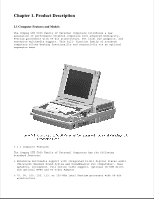 2
2 -
 3
3 -
 4
4 -
 5
5 -
 6
6 -
 7
7 -
8
-
9
-
10
-
11
-
12
-
13
-
14
-
15
-
16
-
17
-
18
-
19
-
20
-
21
-
22
-
23
-
24
-
25
-
26
-
27
-
28
-
29
-
30
-
31
-
32
-
33
-
34
-
35
-
36
-
37
-
38
-
39
-
40
-
41
-
42
-
43
-
44
-
45
-
46
-
47
-
48
-
49
-
50
-
51
-
52
-
53
-
54
-
55
-
56
-
57
-
58
-
59
-
60
-
61
-
62
-
63
-
64
-
65
-
66
-
67
-
68
-
69
-
70
-
71
-
72
-
73
-
74
-
75
-
76
-
77
-
78
-
79
-
80
-
81
-
82
-
83
-
84
-
85
-
86
-
87
-
88
-
89
-
90
-
91
-
92
-
93
-
94
-
95
-
96
-
97
-
98
-
99
-
100
-
101
-
102
-
103
-
104
-
105
-
106
-
107
-
108
-
109
-
110
-
111
-
112
-
113
-
114
-
115
-
116
-
117
-
118
-
119
-
120
-
121
-
122
-
123
-
124
-
125
-
126
-
127
-
128
-
129
-
130
-
131
-
132
-
133
-
134
-
135
-
136
-
137
-
138
-
139
-
140
-
141
-
142
-
143
-
144
-
145
-
146
-
147
-
148
-
149
-
150
-
151
-
152
-
153
-
154
-
155
-
156
-
157
-
158
-
159
-
160
-
161
-
162
-
163
-
164
-
165
-
166
-
167
-
168
-
169
-
170
-
171
-
172
-
173
-
174
-
175
-
176
-
177
-
178
-
179
-
180
-
181
-
182
-
183
-
184
-
185
-
186
-
187
-
188
-
189
-
190
-
191
-
192
-
193
-
194
-
195
-
196
-
197
-
198
-
199
-
200
-
201
-
202
-
203
-
204
-
205
-
206
-
207
-
208
-
209
-
210
-
211
-
212
-
213
-
214
-
215
-
216
-
217
-
218
-
219
-
220
-
221
-
222
-
223
-
224
-
225
-
226
-
227
-
228
-
229
-
230
-
231
-
232
-
233
-
234
-
235
-
236
-
237
-
238
-
239
-
240
-
241
-
242
-
243
-
244
-
245
-
246
-
247
-
248
-
249
-
250
-
251
-
252
-
253
-
254
-
255
-
256
-
257
-
258
-
259
-
260
-
261
-
262
-
263
-
264
-
265
-
266
-
267
-
268
-
269
-
270
-
271
-
272
-
273
-
274
-
275
-
276
-
277
-
278
-
279
-
280
-
281
-
282
-
283
-
284
-
285
-
286
-
287
-
288
-
289
-
290
-
291
-
292
-
293
-
294
-
295
-
296
-
297
-
298
-
299
-
300
-
301
-
302
-
303
-
304
-
305
-
306
-
307
-
308
-
309
-
310
-
311
-
312
-
313
-
314
 |
 |

Notice
The information in this guide is subject to change without notice.
Compaq Computer Corporation shall not be liable for technical or editorial
errors or omissions contained herein; nor for incidental or consequential
damages resulting from the furnishing, performance, or use of this
material.
This guide contains information protected by copyright. No part of this
guide may be photocopied or reproduced in any form without prior written
consent from Compaq Computer Corporation.
Copyright 1995, 1996 Compaq Computer Corporation.
All rights reserved. Printed in the U.S.A.
Compaq, Deskpro, LTE, Contura, Presario, ProLinea
Registered U. S. Patent and Trademark Office.
LTE 5000 is a trademark of Compaq Computer Corporation.
Contura Registered in the Philippines Patent Office.
Microsoft, MS-DOS, and Windows are registered trademarks of Microsoft
Corporation.
The software described in this guide is furnished under a license
agreement or nondisclosure agreement. The software may be used or copied
only in accordance with the terms of the agreement.
Product names mentioned herein may be trademarks and/or registered
trademarks of their respective companies.
MAINTENANCE AND SERVICE GUIDE
COMPAQ LTE 5000 FAMILY OF PERSONAL COMPUTERS
First Edition (September 1995)
Second Edition (November 1996)
Documentation Part Number 213583-002
Spare Part Number 213622-002