HP LaserJet 2400 Service Manual - Page 245
General timing diagrams
 |
View all HP LaserJet 2400 manuals
Add to My Manuals
Save this manual to your list of manuals |
Page 245 highlights
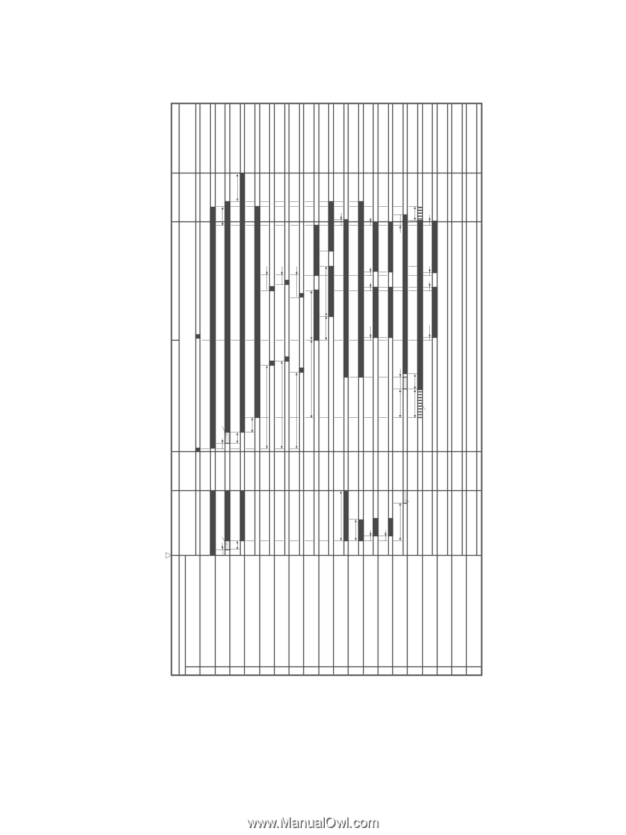
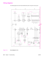
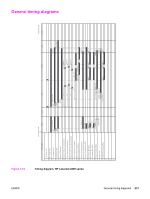
General timing diagrams 231 ENWW Timing diagram, HP LaserJet 2400 series Figure 7-15. SEQUENCE Power Switch ON WAIT 1 Print Command 2 Main Motor (M1) 3 Fuser Heater (H1) 4 Fuser Motor (M2) 5 Scanner Motor(M3) 6 Cassette Pickup Solenoid (SL1) 7 Tray 1 Pickup Solenoid (SL2) 8 Paper Feeder Pickup Solenoid (SL3) 9 Top of Page Sensor (PS801) 10 Delivery Sensor (PS803) 11 Primary Charging Bias (AC) 12 Primary Charging Bias (DC) 13 Developing Bias (AC) 14 Developing Bias (DC) 15 Transfer Charging Bias 16 Laser Diode 17 LASER BEAM signal (BD) 18 19 20 0.2 120°C Control 0.5 About 7.4 About 3.3 About 0.22 About 0.22 About 6.2 Negative Bias STBY INTR PRINT LSTR 0.2 120°C Control 0.5 0.7 3.7 3.9 3.2 3.0 About 0.7 About 0.4 About 1.2 About 1.39 About 1.05 About 1.46 0.8 1.43 0.27 0.09 0.23 0.09 0.23 1.5 About 0.44 About 1.5 0.78 Forced emission 0.16 0.23 0.16 0.34 0.47 0.23 (Unit:Seconds) STBY General timing diagrams
-
 1
1 -
2
-
3
-
4
-
5
-
6
-
7
-
8
-
9
-
10
-
11
-
12
-
13
-
14
-
15
-
16
-
17
-
18
-
19
-
20
-
21
-
22
-
23
-
24
-
25
-
26
-
27
-
28
-
29
-
30
-
31
-
32
-
33
-
34
-
35
-
36
-
37
-
38
-
39
-
40
-
41
-
42
-
43
-
44
-
45
-
46
-
47
-
48
-
49
-
50
-
51
-
52
-
53
-
54
-
55
-
56
-
57
-
58
-
59
-
60
-
61
-
62
-
63
-
64
-
65
-
66
-
67
-
68
-
69
-
70
-
71
-
72
-
73
-
74
-
75
-
76
-
77
-
78
-
79
-
80
-
81
-
82
-
83
-
84
-
85
-
86
-
87
-
88
-
89
-
90
-
91
-
92
-
93
-
94
-
95
-
96
-
97
-
98
-
99
-
100
-
101
-
102
-
103
-
104
-
105
-
106
-
107
-
108
-
109
-
110
-
111
-
112
-
113
-
114
-
115
-
116
-
117
-
118
-
119
-
120
-
121
-
122
-
123
-
124
-
125
-
126
-
127
-
128
-
129
-
130
-
131
-
132
-
133
-
134
-
135
-
136
-
137
-
138
-
139
-
140
-
141
-
142
-
143
-
144
-
145
-
146
-
147
-
148
-
149
-
150
-
151
-
152
-
153
-
154
-
155
-
156
-
157
-
158
-
159
-
160
-
161
-
162
-
163
-
164
-
165
-
166
-
167
-
168
-
169
-
170
-
171
-
172
-
173
-
174
-
175
-
176
-
177
-
178
-
179
-
180
-
181
-
182
-
183
-
184
-
185
-
186
-
187
-
188
-
189
-
190
-
191
-
192
-
193
-
194
-
195
-
196
-
197
-
198
-
199
-
200
-
201
-
202
-
203
-
204
-
205
-
206
-
207
-
208
-
209
-
210
-
211
-
212
-
213
-
214
-
215
-
216
-
217
-
218
-
219
-
220
-
221
-
222
-
223
-
224
-
225
-
226
-
227
-
228
-
229
-
230
-
231
-
232
-
233
-
234
-
235
-
236
-
237
-
238
-
239
-
 240
240 -
 241
241 -
 242
242 -
 243
243 -
 244
244 -
 245
245 -
 246
246 -
 247
247 -
 248
248 -
 249
249 -
 250
250 -
251
-
252
-
253
-
254
-
255
-
256
-
257
-
258
-
259
-
260
-
261
-
262
-
263
-
264
-
265
-
266
-
267
-
268
-
269
-
270
-
271
-
272
-
273
-
274
-
275
-
276
-
277
-
278
-
279
-
280
-
281
-
282
-
283
-
284
-
285
-
286
-
287
-
288
-
289
-
290
-
291
-
292
-
293
-
294
 |
 |