HP LaserJet 5p/mp Service Manual - Page 170
Table 5., Fuser Malfunction, Table 6., Fuser Checks
 |
View all HP LaserJet 5p/mp manuals
Add to My Manuals
Save this manual to your list of manuals |
Page 170 highlights
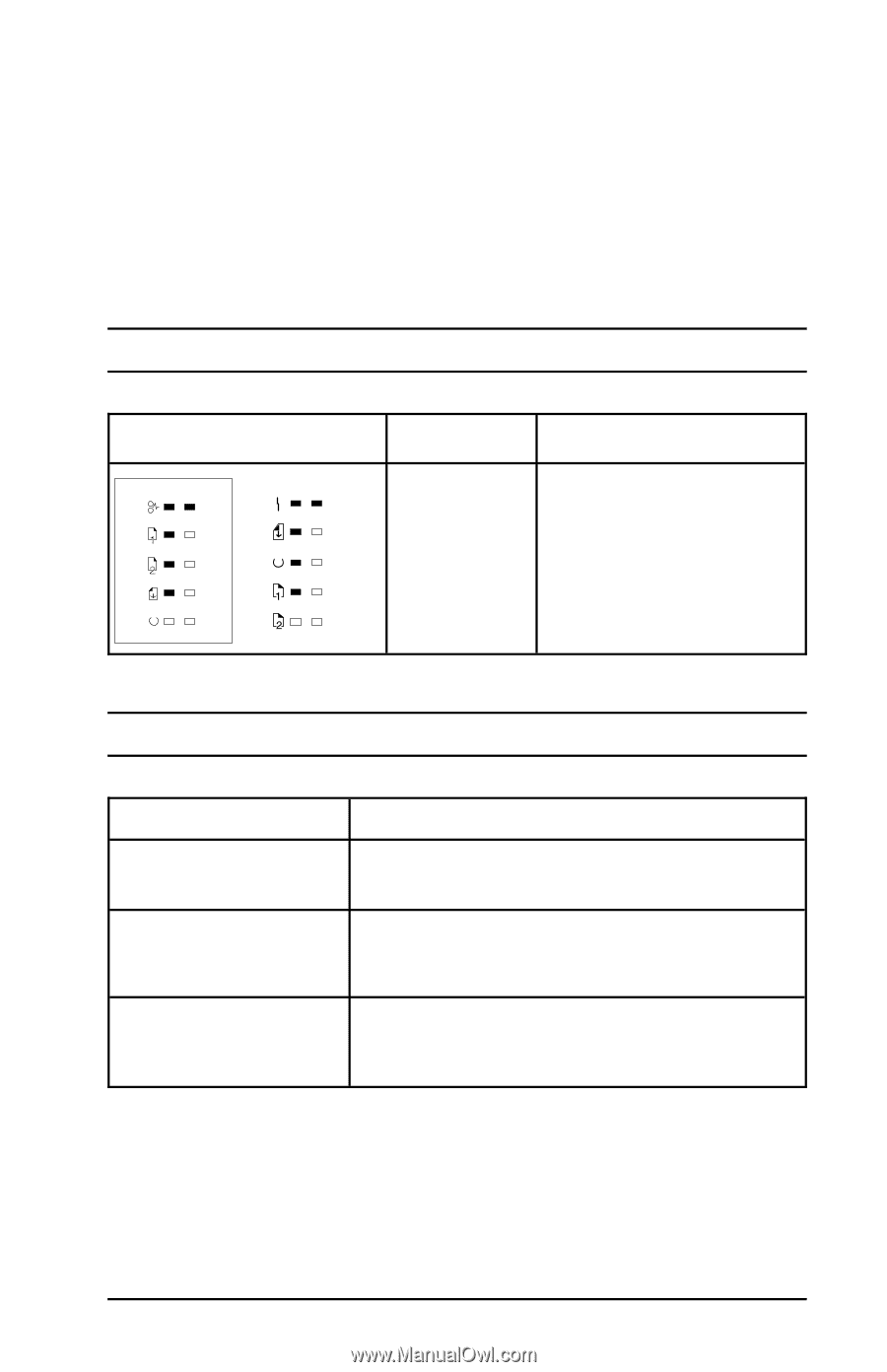
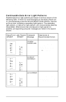
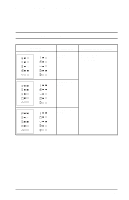
HP LaserJet 5P/5MP, 6P/6MP Printer Service Supplement Troubleshooting Fatal/Service Errors The following tables show fatal/service errors, which are not continuable; no further operation of the printer will occur until corrective action is taken. Table 5. Fuser Malfunction LED Display 5P/5MP 6P/6MP ERROR CODE Description and Recommendation 50 Fuser Malfunction 1. Remove power to the printer for 10 minutes. If this doesn't clear the error: 2. Perform the Fuser Checks shown in Table C-6. 3. Check the Fuses (FU101 and FU201) on the DC Controller PCA. Replace if faulty. 3. Replace the DC Controller PCA. Table 6. Fuser Checks SUSPECTED CAUSE 1. Connector Contact 2. Thermistor wire open. 3. Thermal Fuse. CHECK Ensure that J103 and J204 connectors on the Fusing Assembly are seated securely into the DC Controller PCA connectors (see Figure 6-29 in the Combined Service Manual for locations). Reseat the Fusing Assembly. Remove the Fuser and measure the resistance between connectors J204-1 and J204-2 (see Figure 6-29 in the Combined Service Manual for location). Resistance should read approximately 440 K Ohms at 20 Deg C (room temperature). If the thermistor wire is open, replace the Fusing Assembly. Measure the continuity between connectors J103-1 and J103-2 on the Fuser (see Figure 6-29, the Combined Service Manual for location). It should be approximately 30±5 Ohms for 100-120 VAC or 127±5 Ohms for 220-245 VAC. If the thermal fuse is open, replace the Fusing Assembly. 67
-
 1
1 -
2
-
3
-
4
-
5
-
6
-
7
-
8
-
9
-
10
-
11
-
12
-
13
-
14
-
15
-
16
-
17
-
18
-
19
-
20
-
21
-
22
-
23
-
24
-
25
-
26
-
27
-
28
-
29
-
30
-
31
-
32
-
33
-
34
-
35
-
36
-
37
-
38
-
39
-
40
-
41
-
42
-
43
-
44
-
45
-
46
-
47
-
48
-
49
-
50
-
51
-
52
-
53
-
54
-
55
-
56
-
57
-
58
-
59
-
60
-
61
-
62
-
63
-
64
-
65
-
66
-
67
-
68
-
69
-
70
-
71
-
72
-
73
-
74
-
75
-
76
-
77
-
78
-
79
-
80
-
81
-
82
-
83
-
84
-
85
-
86
-
87
-
88
-
89
-
90
-
91
-
92
-
93
-
94
-
95
-
96
-
97
-
98
-
99
-
100
-
101
-
102
-
103
-
104
-
105
-
106
-
107
-
108
-
109
-
110
-
111
-
112
-
113
-
114
-
115
-
116
-
117
-
118
-
119
-
120
-
121
-
122
-
123
-
124
-
125
-
126
-
127
-
128
-
129
-
130
-
131
-
132
-
133
-
134
-
135
-
136
-
137
-
138
-
139
-
140
-
141
-
142
-
143
-
144
-
145
-
146
-
147
-
148
-
149
-
150
-
151
-
152
-
153
-
154
-
155
-
156
-
157
-
158
-
159
-
160
-
161
-
162
-
163
-
164
-
 165
165 -
 166
166 -
 167
167 -
 168
168 -
 169
169 -
 170
170 -
 171
171 -
 172
172 -
 173
173 -
 174
174 -
 175
175 -
176
-
177
-
178
-
179
-
180
-
181
-
182
-
183
-
184
-
185
-
186
-
187
-
188
-
189
-
190
-
191
-
192
-
193
-
194
-
195
-
196
-
197
-
198
-
199
-
200
-
201
-
202
-
203
-
204
-
205
-
206
-
207
-
208
-
209
-
210
-
211
-
212
-
213
-
214
 |
 |