HP LaserJet M1319 Service Manual - Page 137
Power supply, Reinstallation tip, CAUTION
 |
View all HP LaserJet M1319 manuals
Add to My Manuals
Save this manual to your list of manuals |
Page 137 highlights
Power supply 1. Remove the rear cover and fuser cover. See Rear cover and fuser cover on page 113. 2. Disconnect one spade connector (callout 1) and remove three screws (callout 2). Reinstallation tip The center screw in callout 2 is a ground screw and is different from the others. When reinstalling the power supply, make sure that this screw is used in the center hole. Figure 6-77 Removing the power supply (1 of 5) 1 2 3. Disconnect one FFC (callout 3) and five wire-harness connectors (callout 4) and remove them from the wire loom. CAUTION: Do not bend or fold the FFCs during the removal or reinstallation process. Figure 6-78 Removing the power supply (2 of 5) 3 4 ENWW Product base 119
-
 1
1 -
2
-
3
-
4
-
5
-
6
-
7
-
8
-
9
-
10
-
11
-
12
-
13
-
14
-
15
-
16
-
17
-
18
-
19
-
20
-
21
-
22
-
23
-
24
-
25
-
26
-
27
-
28
-
29
-
30
-
31
-
32
-
33
-
34
-
35
-
36
-
37
-
38
-
39
-
40
-
41
-
42
-
43
-
44
-
45
-
46
-
47
-
48
-
49
-
50
-
51
-
52
-
53
-
54
-
55
-
56
-
57
-
58
-
59
-
60
-
61
-
62
-
63
-
64
-
65
-
66
-
67
-
68
-
69
-
70
-
71
-
72
-
73
-
74
-
75
-
76
-
77
-
78
-
79
-
80
-
81
-
82
-
83
-
84
-
85
-
86
-
87
-
88
-
89
-
90
-
91
-
92
-
93
-
94
-
95
-
96
-
97
-
98
-
99
-
100
-
101
-
102
-
103
-
104
-
105
-
106
-
107
-
108
-
109
-
110
-
111
-
112
-
113
-
114
-
115
-
116
-
117
-
118
-
119
-
120
-
121
-
122
-
123
-
124
-
125
-
126
-
127
-
128
-
129
-
130
-
131
-
 132
132 -
 133
133 -
 134
134 -
 135
135 -
 136
136 -
 137
137 -
 138
138 -
 139
139 -
 140
140 -
 141
141 -
 142
142 -
143
-
144
-
145
-
146
-
147
-
148
-
149
-
150
-
151
-
152
-
153
-
154
-
155
-
156
-
157
-
158
-
159
-
160
-
161
-
162
-
163
-
164
-
165
-
166
-
167
-
168
-
169
-
170
-
171
-
172
-
173
-
174
-
175
-
176
-
177
-
178
-
179
-
180
-
181
-
182
-
183
-
184
-
185
-
186
-
187
-
188
-
189
-
190
-
191
-
192
-
193
-
194
-
195
-
196
-
197
-
198
-
199
-
200
-
201
-
202
-
203
-
204
-
205
-
206
-
207
-
208
-
209
-
210
-
211
-
212
-
213
-
214
-
215
-
216
-
217
-
218
-
219
-
220
-
221
-
222
-
223
-
224
-
225
-
226
-
227
-
228
-
229
-
230
-
231
-
232
-
233
-
234
-
235
-
236
-
237
-
238
-
239
-
240
-
241
-
242
-
243
-
244
-
245
-
246
-
247
-
248
-
249
-
250
-
251
-
252
-
253
-
254
-
255
-
256
-
257
-
258
-
259
-
260
-
261
-
262
-
263
-
264
-
265
-
266
-
267
-
268
-
269
-
270
-
271
-
272
-
273
-
274
-
275
-
276
-
277
-
278
-
279
-
280
-
281
-
282
-
283
-
284
-
285
-
286
-
287
-
288
-
289
-
290
 |
 |

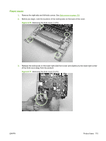
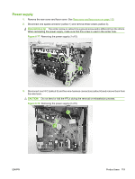
Power supply
1.
Remove the rear cover and fuser cover. See
Rear cover and fuser cover
on page
113
.
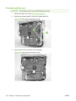
2.
Disconnect one spade connector (callout 1) and remove three screws (callout 2).
Reinstallation tip
The center screw in callout 2 is a ground screw and is different from the others.
When reinstalling the power supply, make sure that this screw is used in the center hole.
Figure 6-77
Removing the power supply (1 of 5)
1
2
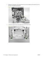
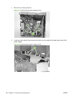
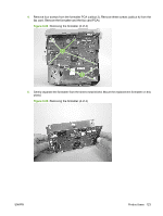
3.
Disconnect one FFC (callout 3) and five wire-harness connectors (callout 4) and remove them from
the wire loom.
CAUTION:
Do not bend or fold the FFCs during the removal or reinstallation process.
Figure 6-78
Removing the power supply (2 of 5)
4
3
ENWW
Product base
119