HP Latex R1000 Site Preparation Guide - Page 29
When you lift the printer with a spreader beam
 |
View all HP Latex R1000 manuals
Add to My Manuals
Save this manual to your list of manuals |
Page 29 highlights
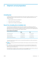
When you lift the printer with a spreader beam, the lifting bars and spreader beam must be long enough so that the lift cables do not touch the printer. The following image illustrates how to lift the printer with a spreader beam: Number 1 Description Spreader beam 2 Slings (4) 3 Lifting bar input and output offset 4 Lifting bars (2) Requirements Working load limit (WLL): 2000 kg (4409 lb) Length: 1000 mm (39.4 in) Minimum WLL (per sling): 1000 kg (2205 lb) Minimum length: 2300 mm (90.6 in) 400 mm (15.7 in) (at each side) 2640 mm (104 in) It is mandatory to position (four) eyebolts 50 mm from each end of the 2 lifting bars. The eyebolt type must be according to the WLL of each sling (1000 kg). It is prohibited to use eyebolts directly screwed to the lifting bar. WARNING! Make sure that the profiles are placed exactly below the stickers on the printer structure when the crane starts to raise the printer. If not, restart the procedure, as printer stability may be compromised. Recommended profiles for the lifting bars: Standard Profile Type UPE 160 A EU UPN 160 B UK PFC150x75x18 A ENWW Moving equipment 25
-
 1
1 -
2
-
3
-
4
-
5
-
6
-
7
-
8
-
9
-
10
-
11
-
12
-
13
-
14
-
15
-
16
-
17
-
18
-
19
-
20
-
21
-
22
-
23
-
 24
24 -
 25
25 -
 26
26 -
 27
27 -
 28
28 -
 29
29 -
 30
30 -
 31
31 -
 32
32 -
 33
33 -
 34
34 -
35
-
36
 |
 |
