HP ML530 ProLiant ML530 High-Performance Technologies - Page 9
standard configuration, PC1600 DDR SDRAM vs. PCI33, two-way interleaved memory - proliant g2 specification
 |
UPC - 720591250669
View all HP ML530 manuals
Add to My Manuals
Save this manual to your list of manuals |
Page 9 highlights
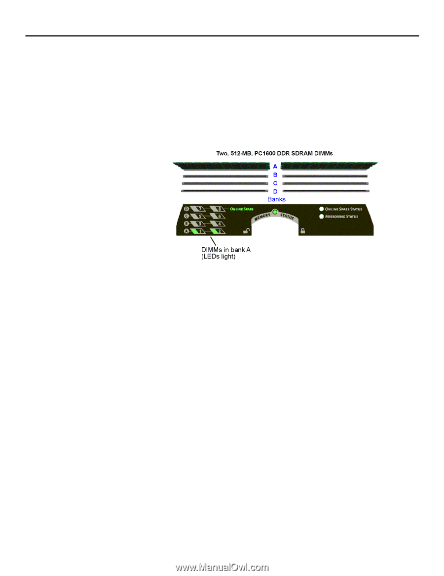
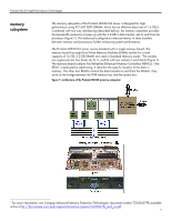
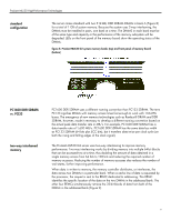
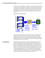
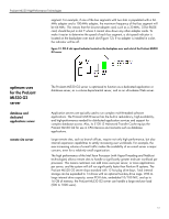
ProLiant ML530 High-Performance Technologies standard configuration The server comes standard with two 512-MB, DDR SDRAM DIMMs in bank A (Figure 8) for a total of 1 GB of system memory. Because the system uses 2-way interleaving, the DIMMs must be installed in pairs, one bank at a time. The DIMMS in each bank must be of the same type and capacity or the performance of the memory subsystem will be degraded. LEDs on the front panel of the memory board show the operating status of the DIMMs. figure 8. ProLiant ML530 G2 system memory banks (top) and front panel of memory board (bottom) PC1600 DDR SDRAM vs. PCI33 two-way interleaved memory PC1600 DDR SDRAM uses a different naming convention than PC133 SDRAM. The term PC133 signifies DIMMs with memory access times fast enough to work with 133-MHz buses. The emergence of new memory technologies such as Rambus® DRAM and DDR SDRAM, however, made it necessary to develop a different naming convention based on the actual peak data transfer rate in MB/s. For example, PC1600 DDR SDRAM has a data transfer rate of 1,600 MB/s. PC1600 DDR SDRAM has the same data bus width as PC133 SDRAM (64 bits plus ECC bits), but it transfers data twice per clock cycle (on both the rising and falling edges of the clock signal). The ProLiant ML530 G2 server uses two-way interleaving to improve memory performance. Two-way interleaving works by dividing memory into multiple 64-bit blocks that can be accessed two at a time, thus doubling the amount of data obtained in a single memory access from 64 bits to 128 bits and reducing the required number of memory accesses. Reducing the number of memory accesses also reduces the number of wait states, further improving performance. When data is written to memory, the memory controller distributes, or interleaves, the data across two DIMMs in a particular bank. When a cache line of data is requested by the processor, the request is sent to the REMC dedicated to addressing. This REMC identifies the specific location of the data on the two DIMMs in the addressed bank. The other four REMCs simultaneously retrieve the 32-bit blocks of data from both of the DIMMs in the addressed bank (Figure 9). 9
-
 1
1 -
2
-
3
-
 4
4 -
 5
5 -
 6
6 -
 7
7 -
 8
8 -
 9
9 -
 10
10 -
 11
11 -
 12
12 -
 13
13 -
 14
14
 |
 |