HP Mini 1117TU HP Mini 1000 Netbook - Maintenance and Service Guide - Page 44
from the system board., to which the keyboard cable is attached,
 |
View all HP Mini 1117TU manuals
Add to My Manuals
Save this manual to your list of manuals |
Page 44 highlights
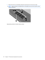
4. Grasp the tabs on the outer edges of the keyboard (1), lift the rear edge of the keyboard (2) until it rests at an angle, and then slide it back (3) until it rests on the display assembly. 5. Release the zero insertion force (ZIF) connector (1) to which the keyboard cable is attached, and then disconnect the cable (2) from the system board. 6. Remove the keyboard. Reverse this procedure to install the keyboard. 36 Chapter 4 Removal and replacement procedures
-
 1
1 -
2
-
3
-
4
-
5
-
6
-
7
-
8
-
9
-
10
-
11
-
12
-
13
-
14
-
15
-
16
-
17
-
18
-
19
-
20
-
21
-
22
-
23
-
24
-
25
-
26
-
27
-
28
-
29
-
30
-
31
-
32
-
33
-
34
-
35
-
36
-
37
-
38
-
 39
39 -
 40
40 -
 41
41 -
 42
42 -
 43
43 -
 44
44 -
 45
45 -
 46
46 -
 47
47 -
 48
48 -
 49
49 -
50
-
51
-
52
-
53
-
54
-
55
-
56
-
57
-
58
-
59
-
60
-
61
-
62
-
63
-
64
-
65
-
66
-
67
-
68
-
69
-
70
-
71
-
72
-
73
-
74
-
75
-
76
-
77
-
78
-
79
-
80
-
81
-
82
-
83
-
84
-
85
-
86
-
87
-
88
-
89
-
90
-
91
-
92
-
93
-
94
-
95
-
96
-
97
-
98
-
99
-
100
-
101
-
102
-
103
-
104
-
105
-
106
-
107
-
108
-
109
-
110
-
111
-
112
-
113
-
114
-
115
-
116
-
117
-
118
-
119
-
120
-
121
-
122
 |
 |

4.
Grasp the tabs on the outer edges of the keyboard
(1)
, lift the rear edge of the keyboard
(2)
until
it rests at an angle, and then slide it back
(3)
until it rests on the display assembly.
5.
Release the zero insertion force (ZIF) connector
(1)
to which the keyboard cable is attached, and
then disconnect the cable
(2)
from the system board.
6.
Remove the keyboard.
Reverse this procedure to install the keyboard.
36
Chapter 4
Removal and replacement procedures