HP Mini CQ10-120SE Compaq Mini CQ10 Notebook PC and Compaq Mini 102 Notebook P - Page 59
Remove the 2 Phillips PM2.0×3.0 screws
 |
View all HP Mini CQ10-120SE manuals
Add to My Manuals
Save this manual to your list of manuals |
Page 59 highlights
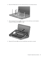
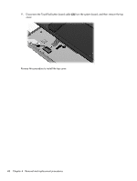
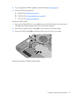
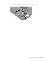
5. If your computer has WWAN capability, remove the SIM (see SIM on page 37). 6. Remove the following components: a. Keyboard (see Keyboard on page 40) b. Hard drive (see Mass storage devices on page 44) c. Top cover (see Top cover on page 46) Remove the WLAN module: 1. Remove the 2 Phillips PM2.0×3.0 screws (1) that secure the WLAN module to the system board. (The edge of the module opposite the slot rises away from the computer.) 2. Disconnect the wireless antenna cables (2) from the terminals on the WLAN module. 3. Remove the WLAN module (3) by pulling the module away from the slot at an angle. Reverse this procedure to install the WLAN module. Component replacement procedures 51
-
 1
1 -
2
-
3
-
4
-
5
-
6
-
7
-
8
-
9
-
10
-
11
-
12
-
13
-
14
-
15
-
16
-
17
-
18
-
19
-
20
-
21
-
22
-
23
-
24
-
25
-
26
-
27
-
28
-
29
-
30
-
31
-
32
-
33
-
34
-
35
-
36
-
37
-
38
-
39
-
40
-
41
-
42
-
43
-
44
-
45
-
46
-
47
-
48
-
49
-
50
-
51
-
52
-
53
-
 54
54 -
 55
55 -
 56
56 -
 57
57 -
 58
58 -
 59
59 -
 60
60 -
 61
61 -
 62
62 -
 63
63 -
 64
64 -
65
-
66
-
67
-
68
-
69
-
70
-
71
-
72
-
73
-
74
-
75
-
76
-
77
-
78
-
79
-
80
-
81
-
82
-
83
-
84
-
85
-
86
-
87
-
88
-
89
-
90
-
91
-
92
-
93
-
94
-
95
-
96
-
97
-
98
-
99
-
100
-
101
-
102
-
103
-
104
-
105
-
106
-
107
-
108
-
109
-
110
-
111
-
112
-
113
-
114
-
115
-
116
-
117
-
118
-
119
 |
 |

5.
If your computer has WWAN capability, remove the SIM (see
SIM
on page
37
).
6.
Remove the following components:
a.
Keyboard (see
Keyboard
on page
40
)
b.
Hard drive (see
Mass storage devices
on page
44
)
c.
Top cover (see
Top cover
on page
46
)
Remove the WLAN module:
1.
Remove the 2 Phillips PM2.0×3.0 screws
(1)
that secure the WLAN module to the system board.
(The edge of the module opposite the slot rises away from the computer.)
2.
Disconnect the wireless antenna cables
(2)
from the terminals on the WLAN module.
3.
Remove the WLAN module
(3)
by pulling the module away from the slot at an angle.
Reverse this procedure to install the WLAN module.
Component replacement procedures
51