HP Model 745 Model 745 Industrial Controller Owner's Guide - Page 72
PMC Bridge Adapter and Expansion Adapter, Preliminary Requirements
 |
View all HP Model 745 manuals
Add to My Manuals
Save this manual to your list of manuals |
Page 72 highlights
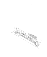
Processor Options Installation PMC Bridge Adapter and Expansion Adapter NOTE: Figure 4-3 4-8 PMC Bridge Adapter and Expansion Adapter This section provides step-by-step instructions for installing the PMC bridge and expansion adapters onto the board computer. When the PMC bridge adapter is installed onto the board computer, the result is a two-board assembly. When both the PMC bridge and expansion adapters are installed onto the board computer, the result is a three-board assembly. Preliminary Requirements Perform the following steps before installing the adapters onto your Board Computer: 1 If the board computer is already installed in your Model 745 chassis, you must remove it. 2 Place the board computer on a static-free mat on a clean, level surface. PMC Bridge Adapter and Expansion Adapter Installation 1 Refer to your PMC card installation manual, and set any configuration switches or jumpers that may be required for your application. 2 On the PMC bridge adapter board, at the sites where you will be installing the PMC card(s), remove the two screws that secure the bezel blank(s), and remove the blank(s). See Figure 4-3. When installing a PMC card, ensure that the O-ring type gasket near the bezel remains in place. 3 Install the PMC card(s) onto the bridge adapter by aligning the front of the card with the front bezel, and the rear of the card with the connectors and keying pin. See Figure 4-3. There are four screws that secure the PMC card from the bottom of the bridge adapter. Installing a PMC Card onto the Bridge Adapter
-
 1
1 -
2
-
3
-
4
-
5
-
6
-
7
-
8
-
9
-
10
-
11
-
12
-
13
-
14
-
15
-
16
-
17
-
18
-
19
-
20
-
21
-
22
-
23
-
24
-
25
-
26
-
27
-
28
-
29
-
30
-
31
-
32
-
33
-
34
-
35
-
36
-
37
-
38
-
39
-
40
-
41
-
42
-
43
-
44
-
45
-
46
-
47
-
48
-
49
-
50
-
51
-
52
-
53
-
54
-
55
-
56
-
57
-
58
-
59
-
60
-
61
-
62
-
63
-
64
-
65
-
66
-
 67
67 -
 68
68 -
 69
69 -
 70
70 -
 71
71 -
 72
72 -
 73
73 -
 74
74 -
 75
75 -
 76
76 -
 77
77 -
78
-
79
-
80
-
81
-
82
-
83
-
84
-
85
-
86
-
87
-
88
-
89
-
90
-
91
-
92
-
93
-
94
-
95
-
96
-
97
-
98
-
99
-
100
-
101
-
102
-
103
-
104
-
105
-
106
-
107
-
108
-
109
-
110
-
111
-
112
-
113
-
114
-
115
-
116
-
117
-
118
-
119
-
120
-
121
-
122
-
123
-
124
-
125
-
126
-
127
-
128
-
129
-
130
-
131
-
132
-
133
-
134
-
135
-
136
-
137
-
138
-
139
-
140
-
141
-
142
-
143
-
144
-
145
-
146
-
147
-
148
-
149
-
150
-
151
-
152
-
153
-
154
-
155
-
156
-
157
-
158
-
159
-
160
-
161
-
162
-
163
-
164
-
165
-
166
-
167
-
168
-
169
-
170
-
171
-
172
-
173
-
174
-
175
-
176
-
177
-
178
-
179
-
180
-
181
-
182
-
183
-
184
-
185
-
186
-
187
-
188
-
189
-
190
-
191
-
192
-
193
-
194
-
195
-
196
-
197
-
198
-
199
-
200
-
201
-
202
-
203
-
204
-
205
-
206
-
207
-
208
-
209
-
210
-
211
-
212
-
213
-
214
-
215
-
216
-
217
-
218
-
219
-
220
 |
 |
