HP P6000 HP StorageWorks Disk enclosure front power UID interconnect board rep - Page 2
Verifying component failure, Removing the power UID interconnect board - hard disk failure warning
 |
View all HP P6000 manuals
Add to My Manuals
Save this manual to your list of manuals |
Page 2 highlights
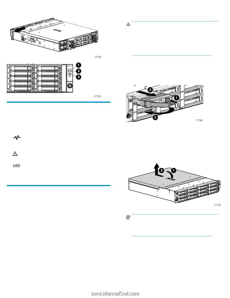
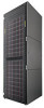
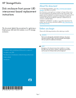
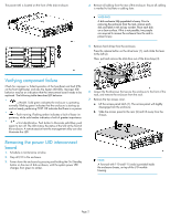
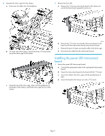
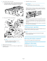
The power UID is located on the front of the disk enclosure. 4. Remove all cabling from the rear of the enclosure. Ensure all cabling is marked to facilitate re-cabling later. WARNING! A disk enclosure fully populated is heavy. Prior to removing the enclosure from the rack, remove each disk and label it with its bay number. Place each disk on a clean surface. If this is not possible, two people are required to remove the enclosure from the rack to prevent injury. 5. Remove hard drives from the enclosure. Press the release button on the drive lever (1), and rotate the lever to the left (2). Then, pull and remove the disk drive out of the drive bays (3). Verifying component failure Check for improper or failed operation of the heartbeat and fault LEDs on the front right bezel, and also the System UID LEDs. Improper LED behavior may be an indication that the interconnect board needs to be replaced. The following table describes LED behavior. • = Health. Solid green indicates the enclosure is operating normally. Blinking green indicates that the enclosure is starting up and not ready, performing POST. Off indicates that there is no power. • = Fault warning. Flashing amber indicates a fault of lesser im- portance, while solid amber indicates a fault of greater importance. • = Unit identification. Push button to illuminate solid blue; push again to turn off. The UID mimics the status of the UID at the front of the enclosure. A remote session from the management utility can also illuminate this LED. 6. Loosen the thumbscrews that secure the enclosure to the front of the rack, and remove the enclosure from the rack. 7. Remove the top access cover. a. Lift the access panel latch (1). The access panel will slightly disengage from the enclosure. b. Slide the access panel to the rear (2) and lift away from the chassis. Removing the power UID interconnect board 1. Schedule a maintenance window. 2. Stop all I/O to the enclosure. 3. Power down the enclosure by pressing and holding the On/Standby button on the rear of disk enclosure, until the system power LED changes from green to amber. NOTE: A Torx tool with T-10 and T-15 ends is provided inside the enclosure chassis, on top of the I/O module housing. Page 2
-
 1
1 -
 2
2 -
 3
3 -
 4
4
 |
 |