HP P6000 HP StorageWorks Small Form Factor Disk Enclosure Backplane replacemen - Page 1
HP P6000 Manual
 |
View all HP P6000 manuals
Add to My Manuals
Save this manual to your list of manuals |
Page 1 highlights
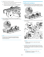
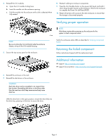
HP StorageWorks Small Form Factor Disk Enclosure Backplane replacement instructions About this document For the latest documentation, go to http://www.hp.com/support/ manuals, and select your product. The information contained herein is subject to change without notice. The only warranties for HP products and services are set forth in the express warranty statements accompanying such products and services. Nothing herein should be construed as constituting an additional warranty. HP shall not be liable for technical or editorial errors or omissions contained herein. WARRANTY STATEMENT: To obtain a copy of the warranty for this product, see the warranty information website: http://www.hp.com/ go/storagewarranty This document details procedures for replacing a failed backplane in an HP StorageWorks Small Form Factor (SFF) Disk Enclosure. Before you begin Observe the following precautions when replacing the backplane. CAUTION: Parts can be damaged by electrostatic discharge. Use proper anti-static protection. Refer to the documentation that shipped with your system for additional information. © Copyright 2009 Hewlett-Packard Development Company, L.P. Fourth edition: February 2010 The information in this document is subject to change without notice. Printed in the US www.hp.com The backplane is located inside the chassis of the disk enclosure. NOTE: Information about this component is also available on the hood label. CAUTION: • These procedures require that all disk drives be removed from the enclosure and returned to their original drive bays. • HP recommends removing disk drives prior to removing the enclosure from the rack. If this is not possible, two people are required to remove the enclosure from the rack to prevent injury. *504220-004* Verifying component failure Use the following methods to verify component failure: • Analyze any failure messages received. HP fault monitoring software provides a recommended action. • View Onboard Administrator system and device status displays for Critical, Major, Minor, and Warning icons. For more information, see the Onboard Administrator user guide. • Check the enclosure LEDs. • Green = Normal operation • Amber = Fault condition Page 1
-
 1
1 -
 2
2 -
 3
3 -
 4
4
 |
 |