HP P6000 HP StorageWorks Small Form Factor Disk Enclosure Backplane replacemen - Page 3
Installing the backplane, Place the drive cage close to the chassis and reconnect all cables
 |
View all HP P6000 manuals
Add to My Manuals
Save this manual to your list of manuals |
Page 3 highlights
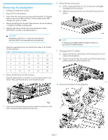
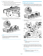
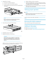
11. Separate the drive cage from the chassis. a. Remove the six T-10 screws (three from each side of the chassis) that secure the drive cage to the chassis (1). b. Grasp the top of the drive cage, slide it off the guideposts on the bottom of the chassis, and lift it out of the chassis (2). Installing the backplane 1. Holding the backplane at an angle, align the backplane with the guides on the base of the chassis and tilt the backplane into position (1). Secure the backplane with the eight T-15 retaining screws (2). 12. Remove the eight T-15 retaining screws from the backplane (1). Then, tilt the backplane away from the drive cage and lift it up and out of the chassis (2). 2. Place the drive cage close to the chassis and reconnect all cables to the backplane. NOTE: Two special screws with long heads are located between the connectors for the I/O modules on the backplane to facilitate removal and replacement. NOTE: All cables are keyed and are uniquely sized to prevent connection errors. 3. Reinstall the drive cage by aligning the keyhole openings on the bottom flange of the drive cage with the guideposts on the bottom of the chassis and then sliding the drive cage into position. Replace the six T-10 screws. NOTE: An additional set of T-10 screws is provided in case the original screws are misplaced. Page 3
-
 1
1 -
 2
2 -
 3
3 -
 4
4
 |
 |
