HP Pavilion 13-b000 Pavilion 13 Notebook PC Maintenance and Service Guide - Page 60
System board, memory modules see
 |
View all HP Pavilion 13-b000 manuals
Add to My Manuals
Save this manual to your list of manuals |
Page 60 highlights
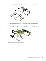
System board Description Spare part number Equipped with an Intel Core i5-4210U 1.70-GHz (SC turbo up to 2.70-GHz) processor (1600MHz FSB, 3.00-MB L3 cache, dual core, 15 W) and the Windows 8 Standard operating system 767819-501 Equipped with an Intel Core i5-4210U 1.70-GHz (SC turbo up to 2.70-GHz) processor (1600MHz FSB, 3.00-MB L3 cache, dual core, 15 W) and a non-Windows 8 operating system 767819-001 Equipped with an Intel Core i3-4030U 1.90-GHz processor (1600-MHz FSB, 3.00-MB L3 cache, 767821-501 dual core, 15 W) and the Windows 8 Standard operating system Equipped with an Intel Core i3-4030U 1.90-GHz processor (1600-MHz FSB, 3.00-MB L3 cache, 767821-001 dual core, 15 W) and a non-Windows 8 operating system Before removing the system board, follow these steps: 1. Shut down the computer. If you are unsure whether the computer is off or in Hibernation, turn the computer on, and then shut it down through the operating system. 2. Disconnect all external devices connected to the computer. 3. Disconnect the power from the computer by first unplugging the power cord from the AC outlet and then unplugging the AC adapter from the computer. 4. Remove the keyboard/top cover (see Keyboard/top cover on page 29), and then remove the following components: a. Battery (see Battery on page 35) b. WLAN module (see WLAN module on page 38) c. Fan (see Fan on page 41) d. Speakers (see Speakers on page 42) e. Display assembly (see Display assembly on page 43) When replacing the system board, be sure that the heat sink (see Heat sink on page 54) and the memory modules (see Memory module on page 56) are removed from the defective system board and installed on the replacement system board. Remove the system board: 1. Release the ZIF connector (1) to which the hard drive cable is attached, and then disconnect the hard drive cable from the system board. 2. Disconnect the power connector cable (2) from the system board. 52 Chapter 5 Removal and replacement procedures
-
 1
1 -
2
-
3
-
4
-
5
-
6
-
7
-
8
-
9
-
10
-
11
-
12
-
13
-
14
-
15
-
16
-
17
-
18
-
19
-
20
-
21
-
22
-
23
-
24
-
25
-
26
-
27
-
28
-
29
-
30
-
31
-
32
-
33
-
34
-
35
-
36
-
37
-
38
-
39
-
40
-
41
-
42
-
43
-
44
-
45
-
46
-
47
-
48
-
49
-
50
-
51
-
52
-
53
-
54
-
 55
55 -
 56
56 -
 57
57 -
 58
58 -
 59
59 -
 60
60 -
 61
61 -
 62
62 -
 63
63 -
 64
64 -
 65
65 -
66
-
67
-
68
-
69
-
70
-
71
-
72
-
73
-
74
-
75
-
76
-
77
-
78
-
79
-
80
-
81
-
82
 |
 |
