HP Pavilion 13-b000 Pavilion 13 Notebook PC Maintenance and Service Guide - Page 61
Remove the heat sink, and system board by sliding them up and to the left at an angle.
 |
View all HP Pavilion 13-b000 manuals
Add to My Manuals
Save this manual to your list of manuals |
Page 61 highlights
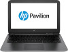
3. Remove the three Phillips PM2.4×5.7 screws (3) that secure the system board to the bottom cover. 4. Flex the left side of the bottom cover (1) until the heat sink has clearance for release. 5. Lift the left side of the heat sink (2) and system board until it rests at an angle. 6. Remove the heat sink (3) and system board by sliding them up and to the left at an angle. Reverse this procedure to install the system board. Component replacement procedures 53
-
 1
1 -
2
-
3
-
4
-
5
-
6
-
7
-
8
-
9
-
10
-
11
-
12
-
13
-
14
-
15
-
16
-
17
-
18
-
19
-
20
-
21
-
22
-
23
-
24
-
25
-
26
-
27
-
28
-
29
-
30
-
31
-
32
-
33
-
34
-
35
-
36
-
37
-
38
-
39
-
40
-
41
-
42
-
43
-
44
-
45
-
46
-
47
-
48
-
49
-
50
-
51
-
52
-
53
-
54
-
55
-
 56
56 -
 57
57 -
 58
58 -
 59
59 -
 60
60 -
 61
61 -
 62
62 -
 63
63 -
 64
64 -
 65
65 -
 66
66 -
67
-
68
-
69
-
70
-
71
-
72
-
73
-
74
-
75
-
76
-
77
-
78
-
79
-
80
-
81
-
82
 |
 |

3.
Remove the three Phillips PM2.4×5.7 screws
(3)
that secure the system board to the bottom cover.
4.
Flex the left side of the bottom cover
(1)
until the heat sink has clearance for release.
5.
Lift the left side of the heat sink
(2)
and system board until it rests at an angle.
6.
Remove the heat sink
(3)
and system board by sliding them up and to the left at an angle.
Reverse this procedure to install the system board.
Component replacement procedures
53