HP Pavilion 14-b100 HP Pavilion 14 Sleekbook and HP Pavilion 14 Ultrabook Main - Page 63
The heat sink on your system board may appear different from the heat sink shown.
 |
View all HP Pavilion 14-b100 manuals
Add to My Manuals
Save this manual to your list of manuals |
Page 63 highlights
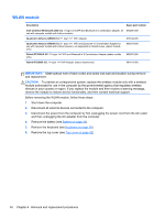
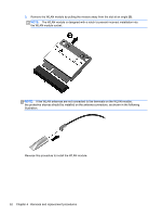
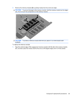
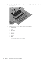
4. Remove the battery (see Battery on page 34). 5. Remove the keyboard (see Keyboard on page 38). 6. Remove the top cover (see Top cover on page 42). 7. Remove the hard drive (see Hard drive on page 46). 8. Remove the USB board (see USB board/audio jack on page 49). 9. Remove the WLAN (see WLAN module on page 50). After removing the system board, be sure that the following components are removed from the defective system board and installed on the replacement system board: ● Memory module (see Memory module on page 58) ● RTC battery (see RTC battery on page 61) ● Heat sink (see Heat sink on page 65) ● PCH heat sink (see PCH heat sink on page 64) ● mSATA solid-state drive (see mSATA solid-state drive on page 62) Remove the system board: NOTE: The heat sink on your system board may appear different from the heat sink shown. 1. Disconnect the following cables from the system board: ● Display panel cable (1) ● Speaker cable (2) ● Fan power connector (3) 2. Remove the power connector bracket Phillips screw (1) and remove the power connector bracket (2). Component replacement procedures 55
-
 1
1 -
2
-
3
-
4
-
5
-
6
-
7
-
8
-
9
-
10
-
11
-
12
-
13
-
14
-
15
-
16
-
17
-
18
-
19
-
20
-
21
-
22
-
23
-
24
-
25
-
26
-
27
-
28
-
29
-
30
-
31
-
32
-
33
-
34
-
35
-
36
-
37
-
38
-
39
-
40
-
41
-
42
-
43
-
44
-
45
-
46
-
47
-
48
-
49
-
50
-
51
-
52
-
53
-
54
-
55
-
56
-
57
-
 58
58 -
 59
59 -
 60
60 -
 61
61 -
 62
62 -
 63
63 -
 64
64 -
 65
65 -
 66
66 -
 67
67 -
 68
68 -
69
-
70
-
71
-
72
-
73
-
74
-
75
-
76
-
77
-
78
-
79
-
80
-
81
-
82
-
83
-
84
-
85
-
86
-
87
-
88
-
89
-
90
-
91
-
92
-
93
-
94
-
95
-
96
-
97
-
98
-
99
-
100
-
101
-
102
-
103
-
104
-
105
-
106
-
107
-
108
-
109
 |
 |
