HP Pavilion 14-b100 HP Pavilion 14 Sleekbook and HP Pavilion 14 Ultrabook Main - Page 78
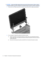
Display assembly, Remove the Phillips M screw
 |
View all HP Pavilion 14-b100 manuals
Add to My Manuals
Save this manual to your list of manuals |
Page 78 highlights
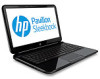
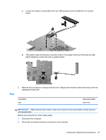
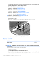
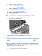
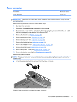
3. Disconnect the power from the computer by first unplugging the power cord from the AC outlet and then unplugging the AC adapter from the computer. 4. Remove the battery (see Battery on page 34). 5. Remove the keyboard (see Keyboard on page 38). 6. Remove the top cover (see Top cover on page 42). 7. Remove the hard drive (see Hard drive on page 46). 8. Remove the USB board (see USB board/audio jack on page 49). 9. Remove the WLAN (see WLAN module on page 50). 10. Remove the system board (see System board on page 53). Remove the RJ-45 cover: 1. Remove the Phillips M screw (1) for the RJ-45 cover. 2. Lift the RJ-45 cover (2) to remove it from the base enclosure. Reverse these procedures to replace the RJ-45 cover. Display assembly Description Antenna Kit (includes left and right wireless antenna cables and transceivers) Display Panel Cable Kit (includes display panel cable and webcam/microphone module cable) Back cover: ● Ruby red ● Silver ● Sparkling black Display Hinge Kit (includes left and right display hinges and brackets) Webcam/microphone module Spare part number 697913-001 697911-001 697909-001 704381-001 697910-001 697908-001 697903-001 70 Chapter 4 Removal and replacement procedures
-
 1
1 -
2
-
3
-
4
-
5
-
6
-
7
-
8
-
9
-
10
-
11
-
12
-
13
-
14
-
15
-
16
-
17
-
18
-
19
-
20
-
21
-
22
-
23
-
24
-
25
-
26
-
27
-
28
-
29
-
30
-
31
-
32
-
33
-
34
-
35
-
36
-
37
-
38
-
39
-
40
-
41
-
42
-
43
-
44
-
45
-
46
-
47
-
48
-
49
-
50
-
51
-
52
-
53
-
54
-
55
-
56
-
57
-
58
-
59
-
60
-
61
-
62
-
63
-
64
-
65
-
66
-
67
-
68
-
69
-
70
-
71
-
72
-
 73
73 -
 74
74 -
 75
75 -
 76
76 -
 77
77 -
 78
78 -
 79
79 -
 80
80 -
 81
81 -
 82
82 -
 83
83 -
84
-
85
-
86
-
87
-
88
-
89
-
90
-
91
-
92
-
93
-
94
-
95
-
96
-
97
-
98
-
99
-
100
-
101
-
102
-
103
-
104
-
105
-
106
-
107
-
108
-
109
 |
 |