HP Pavilion 14-n000 Maintenance and Service Guide - Page 101
Heat sink assembly, Memory module see
 |
View all HP Pavilion 14-n000 manuals
Add to My Manuals
Save this manual to your list of manuals |
Page 101 highlights
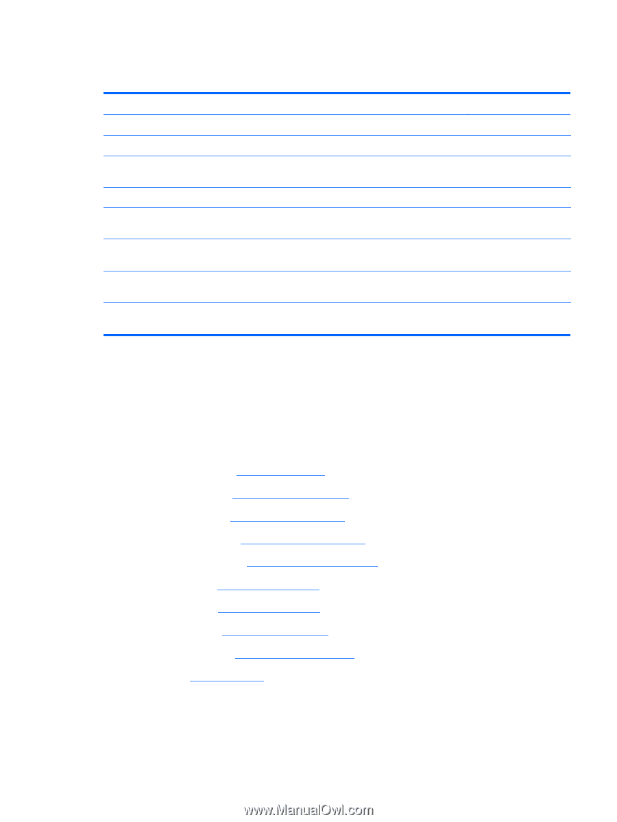
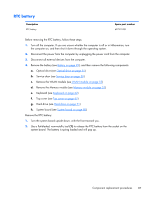
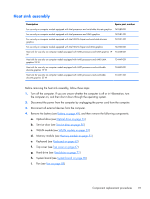
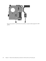
Heat sink assembly Description Spare part number For use only on computer models equipped with Intel processors and switchable discrete graphics 742582-001 For use only on computer models equipped with Intel processors and UMA graphics 742581-001 For use only on computer models equipped with Intel HM76 chipset and switchable discrete graphics 742331-001 For use only on computer models equipped with Intel HM76 chipset and UMA graphics 742330-001 Heat sink for use only on computer models equipped with AMD processors and UMA graphics 19 734448-001 W Heat sink for use only on computer models equipped with AMD processors and AMD UMA graphics 25 W 734449-001 Heat sink for use only on computer models equipped with AMD processors and switchable discrete graphics 19 W 734450-001 Heat sink for use only on computer models equipped with AMD processors and switchable discrete graphics 25 W 734451-001 Before removing the heat sink assembly, follow these steps: 1. Turn off the computer. If you are unsure whether the computer is off or in Hibernation, turn the computer on, and then shut it down through the operating system. 2. Disconnect the power from the computer by unplugging the power cord from the computer. 3. Disconnect all external devices from the computer. 4. Remove the battery (see Battery on page 49), and then remove the following components: a. Optical drive (see Optical drive on page 55) b. Service door (see Service door on page 50) c. WLAN module (see WLAN module on page 53) d. Memory module (see Memory module on page 51) e. Keyboard (see Keyboard on page 62) f. Top cover (see Top cover on page 67) g. Hard drive (see Hard drive on page 71) h. System board (see System board on page 80) i. Fan (see Fan on page 89) Component replacement procedures 91
-
 1
1 -
2
-
3
-
4
-
5
-
6
-
7
-
8
-
9
-
10
-
11
-
12
-
13
-
14
-
15
-
16
-
17
-
18
-
19
-
20
-
21
-
22
-
23
-
24
-
25
-
26
-
27
-
28
-
29
-
30
-
31
-
32
-
33
-
34
-
35
-
36
-
37
-
38
-
39
-
40
-
41
-
42
-
43
-
44
-
45
-
46
-
47
-
48
-
49
-
50
-
51
-
52
-
53
-
54
-
55
-
56
-
57
-
58
-
59
-
60
-
61
-
62
-
63
-
64
-
65
-
66
-
67
-
68
-
69
-
70
-
71
-
72
-
73
-
74
-
75
-
76
-
77
-
78
-
79
-
80
-
81
-
82
-
83
-
84
-
85
-
86
-
87
-
88
-
89
-
90
-
91
-
92
-
93
-
94
-
95
-
 96
96 -
 97
97 -
 98
98 -
 99
99 -
 100
100 -
 101
101 -
 102
102 -
 103
103 -
 104
104 -
 105
105 -
 106
106 -
107
-
108
-
109
-
110
-
111
-
112
-
113
-
114
-
115
-
116
-
117
-
118
-
119
-
120
-
121
-
122
-
123
-
124
-
125
-
126
-
127
-
128
-
129
-
130
-
131
-
132
-
133
-
134
-
135
-
136
-
137
-
138
-
139
-
140
-
141
-
142
 |
 |