HP Pavilion 15-ab000 Pavilion Notebook AMD Maintenance and Service Guide 1 - Page 74
The display cable is available using spare part number 811222-001 for touch displays.
 |
View all HP Pavilion 15-ab000 manuals
Add to My Manuals
Save this manual to your list of manuals |
Page 74 highlights
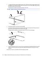
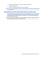
5. To remove the wireless antenna cables and transceivers, release the wireless antenna cables from the clips (1) built into the display enclosure, peel the transceivers from the enclosure (2), and then remove the antenna cables and transceivers (3). The antennas are available using spare part number 811201-001. NOTE: Number of antennas and transceivers may vary. 6. Disconnect the cable from the touch control board (1). 7. To remove the display/webcam cable, remove the cable from the clips built into the display enclosure (2), and then remove the cable from the display enclosure (3). The display cable is available using spare part number 811222-001 for touch displays. 8. If replacing the display enclosure, be sure that the subcomponents (including the webcam/microphone module, the antenna receivers, and all associated cables and hardware) are transferred to the new enclosure. Reverse this procedure to reassemble and install the display assembly. 66 Chapter 6 Removal and replacement procedures for Authorized Service Provider parts
-
 1
1 -
2
-
3
-
4
-
5
-
6
-
7
-
8
-
9
-
10
-
11
-
12
-
13
-
14
-
15
-
16
-
17
-
18
-
19
-
20
-
21
-
22
-
23
-
24
-
25
-
26
-
27
-
28
-
29
-
30
-
31
-
32
-
33
-
34
-
35
-
36
-
37
-
38
-
39
-
40
-
41
-
42
-
43
-
44
-
45
-
46
-
47
-
48
-
49
-
50
-
51
-
52
-
53
-
54
-
55
-
56
-
57
-
58
-
59
-
60
-
61
-
62
-
63
-
64
-
65
-
66
-
67
-
68
-
 69
69 -
 70
70 -
 71
71 -
 72
72 -
 73
73 -
 74
74 -
 75
75 -
 76
76 -
 77
77 -
 78
78 -
 79
79 -
80
-
81
-
82
-
83
-
84
-
85
-
86
-
87
-
88
-
89
-
90
-
91
-
92
-
93
-
94
-
95
-
96
-
97
-
98
-
99
-
100
-
101
-
102
-
103
-
104
-
105
-
106
-
107
-
108
-
109
-
110
 |
 |
