HP Pavilion 15-bj000 Maintenance and Service Guide - Page 74
Display assembly, non-touch, unplugging the power cord from the AC outlet and then
 |
View all HP Pavilion 15-bj000 manuals
Add to My Manuals
Save this manual to your list of manuals |
Page 74 highlights
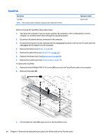
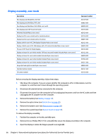
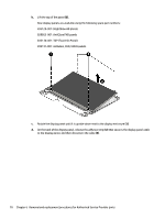
Display assembly, non-touch Description Raw display panel (BrightView, HD, flat) Raw display panel (AntiGlare, FHD, slim) Raw display panel (AntiGlare, FHD, UWVA, non-touch) Raw display panel (TOP (Touch On Panel)) Antennas (include Mylar screw covers) Display bezel for use in models with a standard webcam Display bezel for use in models with a 3D camera Display cable for use in HD, SVA displays (includes Mylar screw covers) Display cable for use in FHD, SVA displays with a 3D camera (includes Mylar screw covers) For use in TOP (Touch On Panel) displays Display enclosure for use in black models TOP (touch on panel) models (includes Mylar screw covers) Display enclosure for use in white models (includes Mylar screw covers) Display enclosure for use in silver models (includes Mylar screw covers) Display enclosure for use in black models (includes Mylar screw covers) Hinges (left and right) (include Mylar screw covers) Standard camera module 3D camera module Spare part number 833129-001 839853-001 809999-001 833130-001 833120-001 833126-001 840477-001 833133-001 840454-001 833134-001 833122-001 840290-001 841942-001 843213-001 809030-001 833127-001 833128-001 Before removing the display assembly, follow these steps: 1. Shut down the computer. If you are unsure whether the computer is off or in Hibernation, turn the computer on, and then shut it down through the operating system. 2. Disconnect all external devices connected to the computer. 3. Disconnect the power from the computer by first unplugging the power cord from the AC outlet and then unplugging the AC adapter from the computer. 4. Remove the battery (see Battery on page 34). 5. Remove the optical drive (see Optical drive on page 35). 6. Remove the bottom cover (see Bottom cover on page 38). 7. Remove the system board (see System board on page 56). To remove the display assembly: 1. Position the computer on its side, partially open. 2. Remove the two Phillips PM2.5×5.0 screws (1) that secure the display assembly to the computer. 3. Open the display to rotate the hinges upward to an angle (2). 66 Chapter 6 Removal and replacement procedures for Authorized Service Provider parts
-
 1
1 -
2
-
3
-
4
-
5
-
6
-
7
-
8
-
9
-
10
-
11
-
12
-
13
-
14
-
15
-
16
-
17
-
18
-
19
-
20
-
21
-
22
-
23
-
24
-
25
-
26
-
27
-
28
-
29
-
30
-
31
-
32
-
33
-
34
-
35
-
36
-
37
-
38
-
39
-
40
-
41
-
42
-
43
-
44
-
45
-
46
-
47
-
48
-
49
-
50
-
51
-
52
-
53
-
54
-
55
-
56
-
57
-
58
-
59
-
60
-
61
-
62
-
63
-
64
-
65
-
66
-
67
-
68
-
 69
69 -
 70
70 -
 71
71 -
 72
72 -
 73
73 -
 74
74 -
 75
75 -
 76
76 -
 77
77 -
 78
78 -
 79
79 -
80
-
81
-
82
-
83
-
84
-
85
-
86
-
87
-
88
-
89
-
90
-
91
-
92
-
93
-
94
-
95
-
96
-
97
-
98
-
99
-
100
-
101
-
102
-
103
-
104
-
105
-
106
-
107
-
108
-
109
-
110
-
111
-
112
-
113
-
114
-
115
-
116
-
117
-
118
 |
 |