HP Pavilion 15-bj000 Maintenance and Service Guide - Page 85
Non-3D webcam, Remove the Phillips PM2.0×2.0 screw
 |
View all HP Pavilion 15-bj000 manuals
Add to My Manuals
Save this manual to your list of manuals |
Page 85 highlights
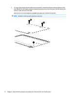
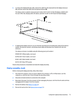
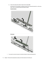
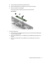
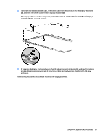
a. Position the display assembly with the top edge toward you. b. Remove the Phillips PM2.0×2.0 screw (1) that secures the module to the display. c. Remove the module from the display (2). The microphone module is available using spare part number 833148-001. Non-3D webcam 4. To remove the display panel: a. Lift the tape that secures the display cable to the connector on the back of the panel (1), and then disconnect the display cable (2). b. Remove the two Phillips PM2.0×1.5 screws (3) that secure the display panel to the bottom of the enclosure. c. Remove the two Phillips PM2.0×2.0 screws (4) that secure the display panel to the top of the enclosure. Component replacement procedures 77
-
 1
1 -
2
-
3
-
4
-
5
-
6
-
7
-
8
-
9
-
10
-
11
-
12
-
13
-
14
-
15
-
16
-
17
-
18
-
19
-
20
-
21
-
22
-
23
-
24
-
25
-
26
-
27
-
28
-
29
-
30
-
31
-
32
-
33
-
34
-
35
-
36
-
37
-
38
-
39
-
40
-
41
-
42
-
43
-
44
-
45
-
46
-
47
-
48
-
49
-
50
-
51
-
52
-
53
-
54
-
55
-
56
-
57
-
58
-
59
-
60
-
61
-
62
-
63
-
64
-
65
-
66
-
67
-
68
-
69
-
70
-
71
-
72
-
73
-
74
-
75
-
76
-
77
-
78
-
79
-
 80
80 -
 81
81 -
 82
82 -
 83
83 -
 84
84 -
 85
85 -
 86
86 -
 87
87 -
 88
88 -
 89
89 -
 90
90 -
91
-
92
-
93
-
94
-
95
-
96
-
97
-
98
-
99
-
100
-
101
-
102
-
103
-
104
-
105
-
106
-
107
-
108
-
109
-
110
-
111
-
112
-
113
-
114
-
115
-
116
-
117
-
118
 |
 |
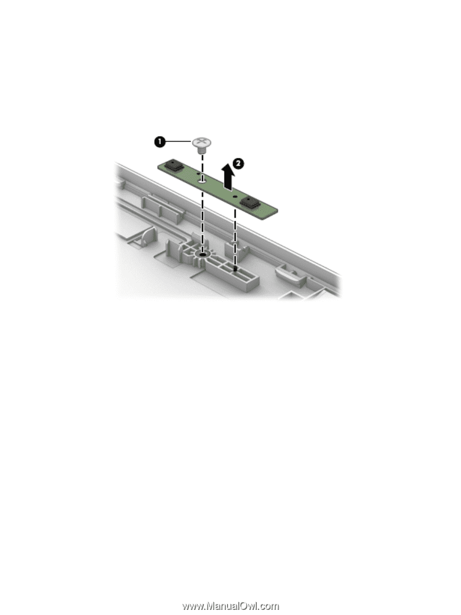
a.
Position the display assembly with the top edge toward you.
b.
Remove the Phillips PM2.0×2.0 screw
(1)
that secures the module to the display.
c.
Remove the module from the display
(2)
.
The microphone module is available using spare part number 833148-001.
Non-3D webcam
4.
To remove the display panel:
a.
Lift the tape that secures the display cable to the connector on the back of the panel
(1)
, and then
disconnect the display cable
(2)
.
b.
Remove the two Phillips PM2.0×1.5 screws
(3)
that secure the display panel to the bottom of the
enclosure.
c.
Remove the two Phillips PM2.0×2.0 screws
(4)
that secure the display panel to the top of the
enclosure.
Component replacement procedures
77