HP Pavilion dv3-4100 HP Pavilion dv3 Entertainment PC - Maintenance and Servic - Page 82
Display assembly, Memory module/wireless module compartment cover see
 |
View all HP Pavilion dv3-4100 manuals
Add to My Manuals
Save this manual to your list of manuals |
Page 82 highlights
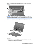
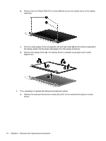
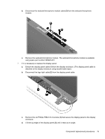
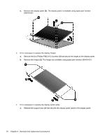
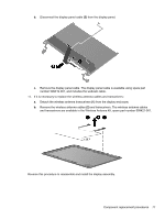
Display assembly Description Spare part number 13.3-in, BrightView, high-definition, LED display assembly (includes display panel cable, webcam/microphone module and cable, 2 WLAN antenna cables and transceivers) In black cherry 603903-001 In brushed aluminum 603905-001 In champagne 606021-001 In shell white 606025-001 In Sonoma red 606023-001 Before removing the display assembly, follow these steps: 1. Shut down the computer. If you are unsure whether the computer is off or in Hibernation, turn the computer on, and then shut it down through the operating system. 2. Disconnect all external devices connected to the computer. 3. Disconnect the power from the computer by first unplugging the power cord from the AC outlet and then unplugging the AC adapter from the computer. 4. Remove the battery (see Battery on page 38), and then remove the following components: a. Hard drive cover (see Hard drive on page 46) b. Memory module/wireless module compartment cover (see Memory module on page 39). c. Keyboard (see Keyboard on page 55) d. Top cover (see Top cover on page 51) Remove the display assembly: 1. Disconnect the display panel cable (1) from the system board and release the cable from the clip (2) built into the base enclosure. 72 Chapter 4 Removal and replacement procedures
-
 1
1 -
2
-
3
-
4
-
5
-
6
-
7
-
8
-
9
-
10
-
11
-
12
-
13
-
14
-
15
-
16
-
17
-
18
-
19
-
20
-
21
-
22
-
23
-
24
-
25
-
26
-
27
-
28
-
29
-
30
-
31
-
32
-
33
-
34
-
35
-
36
-
37
-
38
-
39
-
40
-
41
-
42
-
43
-
44
-
45
-
46
-
47
-
48
-
49
-
50
-
51
-
52
-
53
-
54
-
55
-
56
-
57
-
58
-
59
-
60
-
61
-
62
-
63
-
64
-
65
-
66
-
67
-
68
-
69
-
70
-
71
-
72
-
73
-
74
-
75
-
76
-
 77
77 -
 78
78 -
 79
79 -
 80
80 -
 81
81 -
 82
82 -
 83
83 -
 84
84 -
 85
85 -
 86
86 -
 87
87 -
88
-
89
-
90
-
91
-
92
-
93
-
94
-
95
-
96
-
97
-
98
-
99
-
100
-
101
-
102
-
103
-
104
-
105
-
106
-
107
-
108
-
109
-
110
-
111
-
112
-
113
-
114
-
115
-
116
 |
 |