HP Pavilion dv3-4100 HP Pavilion dv3 Entertainment PC - Maintenance and Servic - Page 83
CAUTION, that secure the display assembly to
 |
View all HP Pavilion dv3-4100 manuals
Add to My Manuals
Save this manual to your list of manuals |
Page 83 highlights
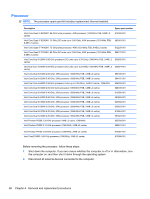
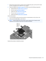
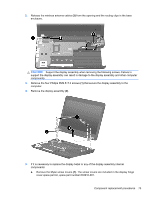
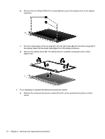
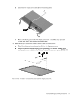
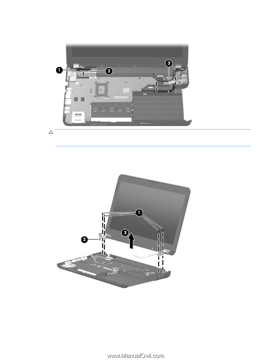
2. Release the wireless antenna cables (3) from the opening and the routing clips in the base enclosure. CAUTION: Support the display assembly when removing the following screws. Failure to support the display assembly can result in damage to the display assembly and other computer components. 3. Remove the four Phillips PM2.5×7.0 screws (1) that secure the display assembly to the computer. 4. Remove the display assembly (2). 5. If it is necessary to replace the display bezel or any of the display assembly internal components: a. Remove the Mylar screw covers (1). The screw covers are included in the display hinge cover spare part kit, spare part number 603910-001. Component replacement procedures 73
-
 1
1 -
2
-
3
-
4
-
5
-
6
-
7
-
8
-
9
-
10
-
11
-
12
-
13
-
14
-
15
-
16
-
17
-
18
-
19
-
20
-
21
-
22
-
23
-
24
-
25
-
26
-
27
-
28
-
29
-
30
-
31
-
32
-
33
-
34
-
35
-
36
-
37
-
38
-
39
-
40
-
41
-
42
-
43
-
44
-
45
-
46
-
47
-
48
-
49
-
50
-
51
-
52
-
53
-
54
-
55
-
56
-
57
-
58
-
59
-
60
-
61
-
62
-
63
-
64
-
65
-
66
-
67
-
68
-
69
-
70
-
71
-
72
-
73
-
74
-
75
-
76
-
77
-
 78
78 -
 79
79 -
 80
80 -
 81
81 -
 82
82 -
 83
83 -
 84
84 -
 85
85 -
 86
86 -
 87
87 -
 88
88 -
89
-
90
-
91
-
92
-
93
-
94
-
95
-
96
-
97
-
98
-
99
-
100
-
101
-
102
-
103
-
104
-
105
-
106
-
107
-
108
-
109
-
110
-
111
-
112
-
113
-
114
-
115
-
116
 |
 |
2.
Release the wireless antenna cables
(3)
from the opening and the routing clips in the base
enclosure.
CAUTION:
Support the display assembly when removing the following screws. Failure to
support the display assembly can result in damage to the display assembly and other computer
components.
3.
Remove the four Phillips PM2.5×7.0 screws
(1)
that secure the display assembly to the
computer.
4.
Remove the display assembly
(2)
.
5.
If it is necessary to replace the display bezel or any of the display assembly internal
components:
a.
Remove the Mylar screw covers
(1)
. The screw covers are included in the display hinge
cover spare part kit, spare part number 603910-001.
Component replacement procedures
73