HP Pavilion x2 - 10-k077nr HP Pavilion x2 Detachable PC (model number 10-k0XX) - Page 25
Removal and replacement procedures, Tablet component replacement procedures, Back cover - screen replacement
 |
View all HP Pavilion x2 - 10-k077nr manuals
Add to My Manuals
Save this manual to your list of manuals |
Page 25 highlights
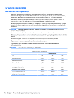
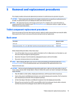
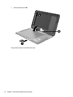
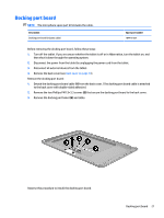
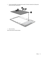
5 Removal and replacement procedures This chapter provides removal and replacement procedures for authorized service provider only parts. CAUTION: Tablet components described in this chapter should only be accessed by an authorized service provider. Accessing these parts can damage the tablet and void the warranty. NOTE: HP continually improves and changes product parts. For complete and current information on supported parts for your computer, go to http://partsurfer.hp.com, select your country or region, and then follow the on-screen instructions. Tablet component replacement procedures There are as many as 20 screws that must be removed, replaced, and/or loosened when servicing the tablet. Make special note of each screw size and location during removal and replacement. Back cover Description Back cover Display panel assembly, 10.1-in, AG, LED, WXGA, TouchScreen (includes bezel and TouchScreen cable) Spare part number 792587-001 784420-001 Before disassembling the tablet, follow these steps: 1. Turn off the tablet. If you are unsure whether the tablet is off or in Hibernation, turn the tablet on, and then shut it down through the operating system. 2. Disconnect the power from the tablet by unplugging the power cord from the tablet. 3. Disconnect all external devices from the tablet. NOTE: When replacing the back cover, be sure to remove the docking port board and cable (see Docking port board on page 21) from the defective back cover and installed on the replacement back cover. Remove the back cover: CAUTION: Before turning the display panel assembly upside down, make sure the work surface is clear of tools, screws, and any other foreign objects. Failure to follow this caution can result in damage to the display panel assembly. 1. Place the tablet on a flat surface, display panel side down, with the power button toward you. 2. Insert a thin, plastic tool (1) between the back cover and the display panel assembly. The first insertion point should be just to the left of the microphone openings. 3. Lift the front edge of the back cover (2) until it separates from the display panel assembly. 4. Release the zero insertion force (ZIF) connector (3) to which the docking port board cable is attached, and then disconnect the docking port board cable from the system board. Tablet component replacement procedures 19
-
 1
1 -
2
-
3
-
4
-
5
-
6
-
7
-
8
-
9
-
10
-
11
-
12
-
13
-
14
-
15
-
16
-
17
-
18
-
19
-
 20
20 -
 21
21 -
 22
22 -
 23
23 -
 24
24 -
 25
25 -
 26
26 -
 27
27 -
 28
28 -
 29
29 -
 30
30 -
31
-
32
-
33
-
34
-
35
-
36
-
37
-
38
-
39
-
40
-
41
-
42
-
43
-
44
-
45
-
46
-
47
-
48
-
49
-
50
-
51
-
52
-
53
 |
 |