HP Pavilion x2 - 10-k077nr HP Pavilion x2 Detachable PC (model number 10-k0XX) - Page 32
System board
 |
View all HP Pavilion x2 - 10-k077nr manuals
Add to My Manuals
Save this manual to your list of manuals |
Page 32 highlights
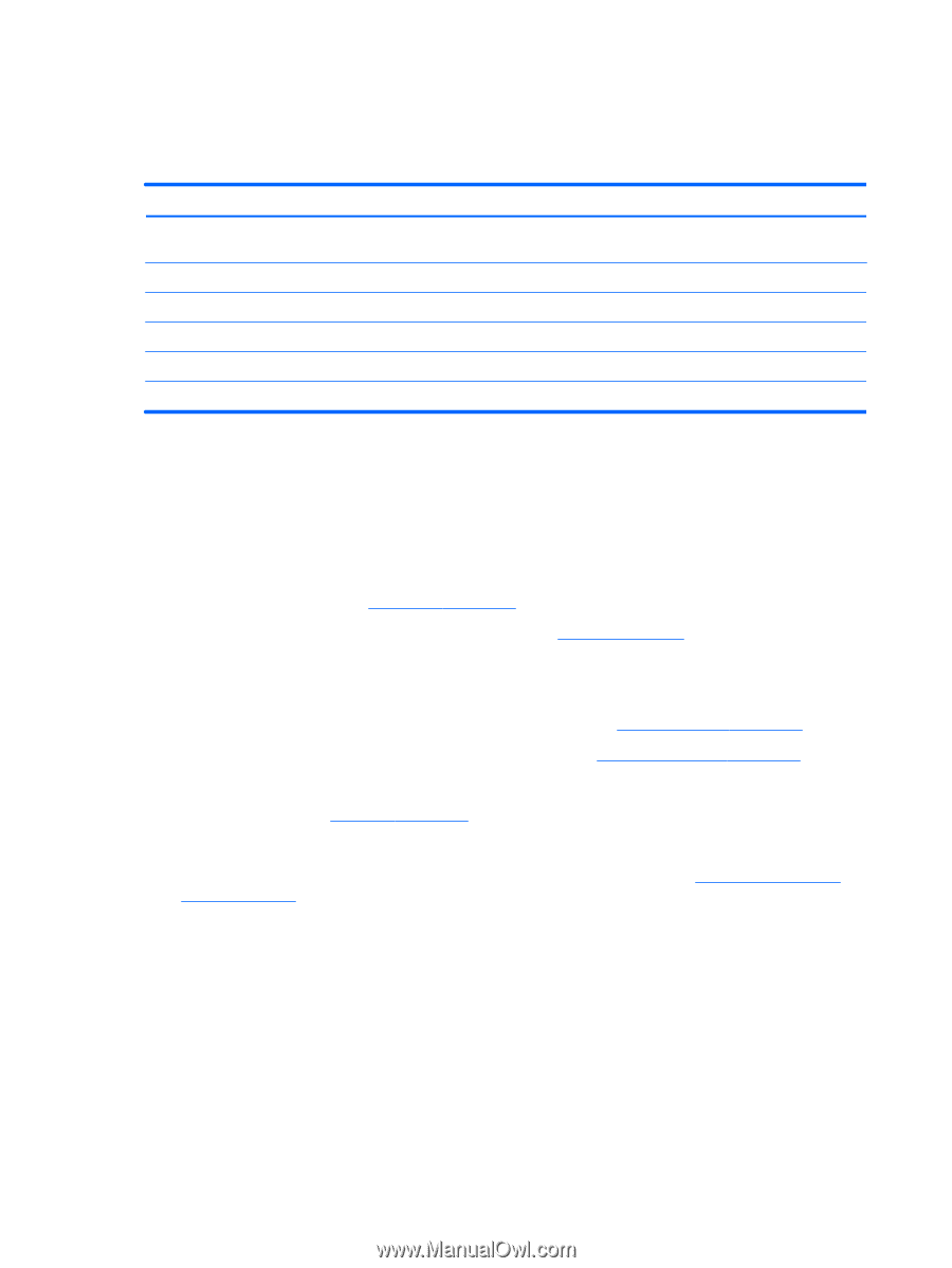
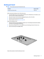
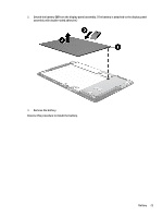
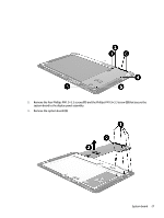
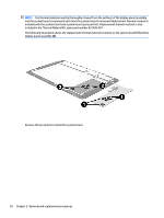
Reverse this procedure to install the audio jack board and cable. System board Description Spare part number System board equipped with an Intel Atom Z3736F 1.33-GHz quad core processor (SoC), a graphics subsystem with UMA memory, and 2.0-GB of DDR3L system memory (includes replacement thermal material) Equipped with a 64-GB eMMC hard drive (SoC) and the Windows 8 Standard operating system 789311-501 Equipped with a 64-GB eMMC hard drive (SoC) and a non-Windows 8 operating system 789311-001 Equipped with a 32-GB eMMC hard drive (SoC) and the Windows 8 Standard operating system 789310-501 Equipped with a 32-GB eMMC hard drive (SoC) and a non-Windows 8 operating system 789310-001 Thermal Material Kit (includes replacement thermal material) 651046-001 Before removing the system board, follow these steps: 1. Turn off the tablet. If you are unsure whether the tablet is off or in Hibernation, turn the tablet on, and then shut it down through the operating system. 2. Disconnect the power from the tablet by unplugging the power cord from the tablet. 3. Disconnect all external devices from the tablet. 4. Remove the back cover (see Back cover on page 19). 5. Disconnect the battery cable from the system board (see Battery on page 22). Remove the system board: 1. Disconnect the following cables from the system board: (1) Audio jack board cable ZIF connector on the system board (see Audio jack board on page 25) (2) Display panel cable ZIF connector on the system board (see Display panel cable on page 24) (3) TouchScreen cable ZIF connectors on the system board (2 connectors) (4) Speaker cable (see Speakers on page 30) (5) Antenna cable from terminal on the system board (6) Power/volume button board cable ZIF connector on the system board (see Power/volume button board on page 33) 26 Chapter 5 Removal and replacement procedures
-
 1
1 -
2
-
3
-
4
-
5
-
6
-
7
-
8
-
9
-
10
-
11
-
12
-
13
-
14
-
15
-
16
-
17
-
18
-
19
-
20
-
21
-
22
-
23
-
24
-
25
-
26
-
 27
27 -
 28
28 -
 29
29 -
 30
30 -
 31
31 -
 32
32 -
 33
33 -
 34
34 -
 35
35 -
 36
36 -
 37
37 -
38
-
39
-
40
-
41
-
42
-
43
-
44
-
45
-
46
-
47
-
48
-
49
-
50
-
51
-
52
-
53
 |
 |