HP Pavilion zv5000 Expansion Base - Maintenance and Service Guide - Page 43
Front Tray Cover
 |
View all HP Pavilion zv5000 manuals
Add to My Manuals
Save this manual to your list of manuals |
Page 43 highlights
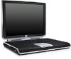
Removal and Replacement Procedures 5.8 Front Tray Cover Spare Part Number Information Front tray cover 347432-001 1. Prepare the Expansion Base for disassembly (Section 5.3). 2. Remove the base plate (Section 5.4). 3. Remove the upper chassis (Section 5.5). 4. Turn the upper chassis upside down with the docking connector and cable facing away from you. 5. Cut all tie-wraps 1 that bundle the Expansion Base cables and secure the RJ-11 modem cable to the chassis. 6. Remove the four PM2.0×4.0 screws 2 that secure the front tray cover to the chassis. Removing the front tray cover screws 5-14 Maintenance and Service Guide
-
 1
1 -
2
-
3
-
4
-
5
-
6
-
7
-
8
-
9
-
10
-
11
-
12
-
13
-
14
-
15
-
16
-
17
-
18
-
19
-
20
-
21
-
22
-
23
-
24
-
25
-
26
-
27
-
28
-
29
-
30
-
31
-
32
-
33
-
34
-
35
-
36
-
37
-
 38
38 -
 39
39 -
 40
40 -
 41
41 -
 42
42 -
 43
43 -
 44
44 -
 45
45 -
 46
46 -
 47
47 -
 48
48 -
49
-
50
-
51
-
52
-
53
-
54
-
55
-
56
-
57
-
58
-
59
-
60
-
61
-
62
-
63
-
64
-
65
-
66
-
67
-
68
-
69
-
70
-
71
-
72
-
73
-
74
 |
 |

5–14
Maintenance and Service Guide
Removal and Replacement Procedures
5.8
Front Tray Cover
1. Prepare the Expansion Base for disassembly
(Section 5.3)
.
2. Remove the base plate
(Section 5.4)
.
3. Remove the upper chassis
(Section 5.5)
.
4. Turn the upper chassis upside down with the docking
connector and cable facing away from you.
5. Cut all tie-wraps
1
that bundle the Expansion Base cables
and secure the RJ-11 modem cable to the chassis.
6. Remove the four PM2.0×4.0 screws
2
that secure the front
tray cover to the chassis.
Removing the front tray cover screws
Spare Part Number Information
Front tray cover
347432-001