HP Presario CQ35-100 Compaq Presario CQ35 Notebook PC - Maintenance and Servic - Page 65
Display assembly, Hard drive see
 |
View all HP Presario CQ35-100 manuals
Add to My Manuals
Save this manual to your list of manuals |
Page 65 highlights
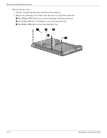
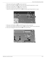
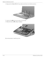
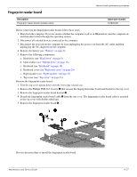
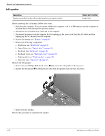
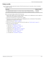
Removal and replacement procedures Display assembly ✎ The display assembly spare part kit includes 2 WLAN antenna transceivers and cables, webcam, microphone, nameplate, and logo. Description 13.3-in BrightView display assembly for use only with computer models equipped with webcam 13.3-in BrightView display assembly for use only with computer models not equipped with webcam Spare part number 531798-001 531799-001 Before removing the display assembly, follow these steps: 1. Shut down the computer. If you are unsure whether the computer is off or in Hibernation, turn the computer on, and then shut it down through the operating system. 2. Disconnect all external devices connected to the computer. 3. Disconnect the power from the computer by first unplugging the power cord from the AC outlet and then unplugging the AC adapter from the computer. 4. Remove the battery (see "Battery" on page 6). 5. Disconnect the wireless antenna cables from the WLAN module (see "WLAN module" on page 11). 6. Remove the following components: a. Hard drive (see "Hard drive" on page 8) b. Optical drive (see "Optical drive" on page 16) c. Keyboard (see "Keyboard" on page 18) d. Keyboard cover (see "Keyboard cover" on page 20) e. Right speaker (see "Right speaker" on page 22) f. Top cover (see "Top cover" on page 23). g. Left speaker (see "Left speaker" on page 28) Maintenance and Service Guide 4-29
-
 1
1 -
2
-
3
-
4
-
5
-
6
-
7
-
8
-
9
-
10
-
11
-
12
-
13
-
14
-
15
-
16
-
17
-
18
-
19
-
20
-
21
-
22
-
23
-
24
-
25
-
26
-
27
-
28
-
29
-
30
-
31
-
32
-
33
-
34
-
35
-
36
-
37
-
38
-
39
-
40
-
41
-
42
-
43
-
44
-
45
-
46
-
47
-
48
-
49
-
50
-
51
-
52
-
53
-
54
-
55
-
56
-
57
-
58
-
59
-
 60
60 -
 61
61 -
 62
62 -
 63
63 -
 64
64 -
 65
65 -
 66
66 -
 67
67 -
 68
68 -
 69
69 -
 70
70 -
71
-
72
-
73
-
74
-
75
-
76
-
77
-
78
-
79
-
80
-
81
-
82
-
83
-
84
-
85
-
86
-
87
-
88
-
89
-
90
-
91
-
92
-
93
-
94
-
95
-
96
-
97
-
98
-
99
-
100
-
101
-
102
-
103
-
104
-
105
-
106
-
107
-
108
-
109
-
110
-
111
-
112
-
113
-
114
-
115
-
116
-
117
-
118
-
119
-
120
-
121
-
122
-
123
-
124
-
125
-
126
-
127
-
128
-
129
-
130
-
131
-
132
-
133
-
134
-
135
 |
 |
