HP Presario CQ35-100 Compaq Presario CQ35 Notebook PC - Maintenance and Servic - Page 67
Remove the display bezel, until the bezel disengages from the display enclosure.
 |
View all HP Presario CQ35-100 manuals
Add to My Manuals
Save this manual to your list of manuals |
Page 67 highlights
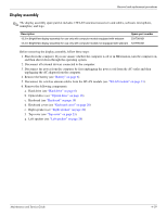
Removal and replacement procedures 4. If it is necessary to replace the display bezel or any of the display assembly internal components, remove the two Mylar screw covers 1 and the two Phillips PM2.5×6.0 screws 2 on the display bezel lower edge. 5. Flex the inside edges of the top edge 1, the left and right sides 2, and the bottom edge 3 of the display bezel until the bezel disengages from the display enclosure. 6. Remove the display bezel 4. The display bezel is available using the following spare part numbers: ❏ 531800-001-for use only with computer models equipped with a webcam ❏ 531801-001-for use only with computer models not equipped with a webcam Maintenance and Service Guide 4-31
-
 1
1 -
2
-
3
-
4
-
5
-
6
-
7
-
8
-
9
-
10
-
11
-
12
-
13
-
14
-
15
-
16
-
17
-
18
-
19
-
20
-
21
-
22
-
23
-
24
-
25
-
26
-
27
-
28
-
29
-
30
-
31
-
32
-
33
-
34
-
35
-
36
-
37
-
38
-
39
-
40
-
41
-
42
-
43
-
44
-
45
-
46
-
47
-
48
-
49
-
50
-
51
-
52
-
53
-
54
-
55
-
56
-
57
-
58
-
59
-
60
-
61
-
 62
62 -
 63
63 -
 64
64 -
 65
65 -
 66
66 -
 67
67 -
 68
68 -
 69
69 -
 70
70 -
 71
71 -
 72
72 -
73
-
74
-
75
-
76
-
77
-
78
-
79
-
80
-
81
-
82
-
83
-
84
-
85
-
86
-
87
-
88
-
89
-
90
-
91
-
92
-
93
-
94
-
95
-
96
-
97
-
98
-
99
-
100
-
101
-
102
-
103
-
104
-
105
-
106
-
107
-
108
-
109
-
110
-
111
-
112
-
113
-
114
-
115
-
116
-
117
-
118
-
119
-
120
-
121
-
122
-
123
-
124
-
125
-
126
-
127
-
128
-
129
-
130
-
131
-
132
-
133
-
134
-
135
 |
 |

Removal and replacement procedures
Maintenance and Service Guide
4–31
4. If it is necessary to replace the display bezel or any of the display assembly internal components, remove the
two Mylar screw covers
1
and the two Phillips PM2.5×6.0 screws
2
on the display bezel lower edge.
5. Flex the inside edges of the top edge
1
, the left and right sides
2
, and the bottom edge
3
of the display bezel
until the bezel disengages from the display enclosure.
6. Remove the display bezel
4
. The display bezel is available using the following spare part numbers:
❏
531800-001—for use only with computer models equipped with a webcam
❏
531801-001—for use only with computer models not equipped with a webcam