HP ProLiant DL280 Memory technology evolution: an overview of system memory te - Page 16
eliminates the parallel stub-bus topology and allows higher memory bandwidth while maintaining or
 |
View all HP ProLiant DL280 manuals
Add to My Manuals
Save this manual to your list of manuals |
Page 16 highlights
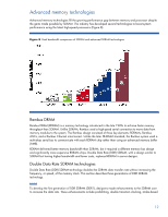
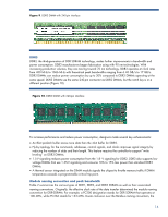
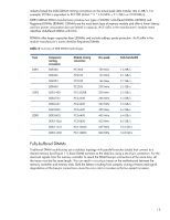
Figure 11. Stub-bus topology Each stub-bus connection creates resistance that can degrade signal integrity. In addition, each DIMM creates an electrical load on the bus. Adding more DIMMs increases the electrical load. As the bus speed increases, these factors decrease the number of supportable DIMMs per channel. For example, Figure 12 shows the number of loads supported per channel at data rates ranging from PC 100 to DDR3 1600. Note that the number of supported loads drops from eight to two as data rates increase to DDR2 800. Figure 12. Maximum number of loads per channel based on DRAM data rate Due to increased cost and board complexity, increasing the number of channels to compensate for the drop in capacity per channel was not a viable option. System designers had two choices: limit memory capacity so that fewer errors occur at higher speeds, or use slower bus speeds and increase the DRAM density. For future generations of high-performance servers, neither option was acceptable. New server designs require improved memory architecture to achieve higher memory bandwidth and capacity. The JEDEC developed the Fully-Buffered DIMM (FB-DIMM) specification, a serial interface that eliminates the parallel stub-bus topology and allows higher memory bandwidth while maintaining or increasing memory capacity. The FB-DIMM architecture has serial links between the memory controller and the FB-DIMMs connected in a daisy chain configuration (Figure 13). Relative to the memory controller, there are ten outbound links and fourteen inbound links, also known as southbound and northbound links, respectively. These serial links 16
-
 1
1 -
2
-
3
-
4
-
5
-
6
-
7
-
8
-
9
-
10
-
 11
11 -
 12
12 -
 13
13 -
 14
14 -
 15
15 -
 16
16 -
 17
17 -
 18
18 -
 19
19
 |
 |
