HP Professional 8000 Highly Parallel System Architecture for Compaq Profession - Page 7
Memory Size, Memory Bus 1, DIMMs, Optimization, Level, for example
 |
View all HP Professional 8000 manuals
Add to My Manuals
Save this manual to your list of manuals |
Page 7 highlights
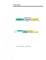
ECG066/1198 TECHNOLOGY BRIEF (cont.) ... memory size and evenly splitting those DIMMs between the two memory channels. Table 1 is a DIMM configuration guide for optimizing performance of dual memory buses. The table shows matched memory sizes on both banks. Other memory configurations are valid. TABLE 1: GUIDE FOR CONFIGURING DUAL MEMORY BUSES TO OPTIMIZE PERFORMANCE Memory Size 32 MB Memory Bus 1 DIMMs - Memory Bus 2 DIMMs 2 x 16 MB Optimization Level * 1 64 MB 2 x 16 MB 2 x 16 MB 1 64 MB - 4 x 16 MB 2 64 MB - 2 x 32 MB 3 128 MB 4 x 16 MB 4 x 16 MB 1 128 MB 2 x 32 MB 2 x 32 MB 2 128 MB - 4 x 32 MB 3 128 MB - 2 x 64 MB 4 256 MB 4 x 32 MB 4 x 32 MB 1 256 MB 2 x 64 MB 2 x 64 MB 2 256 MB - 4 x 64 MB 3 256 MB - 2 x 128 MB 4 512 MB 4 x 64 MB 4 x 64 MB 1 512 MB 6 x 64 MB 2 x 64 MB 2 512 MB 8 x 64 MB - 3 512 MB - 4 x 128 MB 4 1 GB 8 x 64 MB 4 x 128 MB 1 1 GB 4 x 128 MB 4 x 128 MB 2 1 GB 8 x 128 MB - 3 1 GB - 4 x 256 MB 4 2 GB 4 x 256 MB 4 x 256 MB 1 2 GB 8 x 256 MB - 2 * The degree of performance optimization is indicated by a numerical range. Level 1 represents the best performance. Levels 2, 3, and 4 indicate progressively lower performance. The exact performance increase to be gained by optimizing the memory subsystem is highly dependent upon the application. Some applications will see less than 1 percent benefit, while others may see as much as 33 percent. In general, workstation applications with large data sets (for example, MacNeil Schwendler Corporation's NASTRAN Finite Element Analysis software) make better use of the dual memory controllers than most PC productivity applications with small data sets. 7
-
 1
1 -
 2
2 -
 3
3 -
 4
4 -
 5
5 -
 6
6 -
 7
7 -
 8
8 -
 9
9 -
 10
10 -
 11
11 -
 12
12 -
13
 |
 |
