HP RP36000/3 Adding an HP 3 Phase UPS to a parallel configuration Install Inst - Page 1
HP RP36000/3 Manual
 |
View all HP RP36000/3 manuals
Add to My Manuals
Save this manual to your list of manuals |
Page 1 highlights
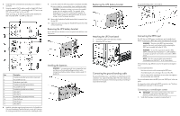
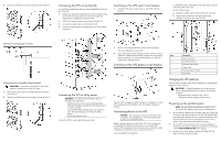
Adding an HP 3 Phase UPS to a parallel configuration Installation Instructions © Copyright 2007, 2013 Hewlett-Packard Development Company, L.P. The information contained herein is subject to change without notice. The only warranties for HP products and services are set forth in the express warranty statements accompanying such products and services. Nothing herein should be construed as constituting an additional warranty. HP shall not be liable for technical or editorial errors or omissions contained herein. Part Number: 456067-003 January 2013 Edition: 3 3 Phase UPS overview The HP 3 Phase UPS features a 6U rack-mount design which offers power protection for loads up to 12000 VA/12000 W. For more information about any of the topics covered in this document, see the UPS user guide located on the documentation CD or HP website (http://www.hp.com/go/rackandpower). Precautions Save these instructions. This document contains important safety instructions that should be followed during installation, operation, and maintenance of the UPS and batteries. WARNING: A risk of personal injury from electric shock and hazardous energy levels exists. The installation of options and routine maintenance and service of this product must be performed by individuals who are knowledgeable about the procedures, precautions, and hazards associated with AC power products. WARNING: To prevent personal injury from earth conductor leakage current: • Do not operate the UPS while disconnected from the utility power source. • Disconnect load devices before disconnecting the UPS from the utility power source. 127 kg 280 lb This symbol indicates that the UPS exceeds the recommended weight for one individual to handle safely. WARNING: To reduce the risk of personal injury or damage to the equipment, observe local occupational health and safety requirements and guidelines for manual material handling. NOTE: The rating label on the device provides the class (A or B) of the equipment. Class B devices have a Federal Communications Commission (FCC) logo or FCC ID on the label. Class A devices do not have an FCC logo or FCC ID on the label. After determining the class of the device, refer to the user guide for complete regulatory compliance notices. UPS kit contents • This document and/or documentation CD • Warranty information • Rails, with mounting hardware for square- and round-holed racks • UPS • Battery modules • Front bezel • Computer interface cable • Rear mounting brackets and associated hardware Tools and materials The following tools are required for installation: • Phillips screwdriver • 10-mm hex-nut wrench • T-25 Torx driver A cage nut-fitting tool is supplied with the rack. Selecting a site WARNING: To prevent fire or electric shock, install the unit in a temperature- and humidity-controlled indoor environment, free of conductive contaminants. When selecting a site, consider the following factors: • Elevated operating ambient temperature-If the equipment is installed in a closed or multi-unit rack assembly, the operating ambient temperature of the rack environment might be greater than room ambient temperature. Install the equipment in an environment compatible with the operating temperature. • Reduced air flow-In the rack, the rate of air flow required for safe operation of the equipment must not be compromised. • Circuit overloading-Consideration should be given to the connection of the equipment to the supply circuit and the effect that overloading of the circuits might have on overcurrent protection and supply wiring. Appropriate consideration of equipment nameplate ratings should be used when addressing this concern. • Reliable earthing-Reliable earthing of rack-mounted equipment should be maintained. Particular attention should be given to supply connections other than direct connections to the branch circuit, such as the use of power strips. • Electrical requirements-All models require a dedicated (unshared) branch circuit, suitably rated for the specific UPS as stated in "Input specifications" in the user guide. Readying the equipment 1. Check the battery recharge date specified on the label that is affixed to the shipping carton. IMPORTANT: Do not use the battery if the recharge date has passed. If the date on the battery recharge date label has passed without the battery being recharged, contact an HP authorized service representative for directions. 2. Transport the packaged unit to its installation location. 3. Unpack the equipment near the rack where the unit will be assembled. Installing the mounting rails WARNING: To reduce the risk of personal injury or damage to the equipment, be sure that: • The leveling feet are extended to the floor. • The full weight of the rack rests on the leveling feet. • The stabilizing feet are attached to the rack if it is a single-rack installation. • The racks are coupled together in multiple-rack installations. • Only one component is extended at a time. A rack may become unstable if more than one component is extended for any reason. WARNING: A risk of personal injury or damage to the equipment exists. Uneven loading of equipment in the rack might cause the rack to become unstable. Install the heavier components first, and then continue to populate the rack from the bottom to the top. CAUTION: Always plan the rack installation so that the heaviest item is on the bottom of the rack. Install the heaviest item first, and continue to populate the rack from the bottom to the top. NOTE: Mounting hardware for square- and round-holed racks is included in the UPS kit. 1. Select the proper holes in the rack for positioning the UPS in the rack. The UPS rails are installed in positions 1 and 12.
-
 1
1 -
 2
2 -
 3
3 -
 4
4 -
 5
5
 |
 |