HP RP36000/3 Adding an HP 3 Phase UPS to a parallel configuration Install Inst - Page 2
Preparing the rails for integrated, shipping, Disconnecting from utility power, Installing the UPS
 |
View all HP RP36000/3 manuals
Add to My Manuals
Save this manual to your list of manuals |
Page 2 highlights
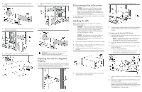
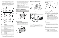
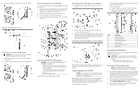
2. Loosen the hex nuts, and extend the brackets to the desired length. 3. Insert screws through the rack into the mounting rail and the front of each mounting bracket. 4. Install cage nuts or clip nuts into the rear of the rack. 5. Insert screws through the mounting rail into the cage nuts or clip nuts. 6. Tighten the hex nuts. IMPORTANT: If preparing the rails for integrated shipping, install the rear mounting brackets. Preparing the rails for integrated shipping If the unit is to be shipped in a rack, install the rear mounting brackets, on both mounting rails, using hex nuts. Wait until the unit is installed and the brackets are adjusted before tightening the nuts. Disconnecting from utility power CAUTION: Power down each UPS before installing an RP12000 UPS into an existing system. Not powering down may cause an unexpected system shutdown or failure. To power down the UPS, see "Powering down the parallel system" in the user guide. For each additional UPS being installed, verify that all circuit breakers are in the Off position. Installing the UPS Before installing the UPS, review and observe all warnings in "Precautions (on page 1)." WARNING: A risk of personal injury or damage to the equipment exists. Uneven loading of equipment in the rack might cause the rack to become unstable. Install the heavier components first, and then continue to populate the rack from the bottom to the top. CAUTION: Always plan the rack installation so that the heaviest item is on the bottom of the rack. Install the heaviest item first, and continue to populate the rack from the bottom to the top. 1. Install the mounting rails ("Installing the mounting rails" on page 1). 2. With one person on each side of the carton, lift the chassis and lower it to the floor in front of the rack. 3. Install the mounting ears on the chassis using the screws provided. 5. Attach the chassis to the rack using the supplied screws. 6. If using the rear mounting brackets, be sure that the bracket tabs are fully inserted into the rear panel cutouts, then tighten the brackets. Configuring the Parallel UPS Card 1. Unpack the Parallel UPS Card, and be sure that the card was not damaged during shipment. NOTE: If installing another X-Slot card, be sure to install the Parallel UPS Card in X-Slot Communication Bay 2. 2. Remove the UPS X-Slot communication bay cover, and retain the screws. 3. Set the jumper pins on the Parallel UPS Card according to the parallel configuration. For three or more paralleled UPSs: o Set the cards of the first and last UPS to Pins 1 and 2. o Set the card for the middle UPS(s) to Pins 2 and 3. 4. With one person on each side, lift the chassis to rail level and slide the chassis on the mounting rails. 4. Install the Parallel UPS Card into an open X-Slot on the rear of the UPS. 5. Repeat steps 1 through 4 to install a Parallel UPS Card into each UPS to be paralleled. The HP 3 Phase UPS parallel system automatically assigns identities to each UPS in the system based on the order in which their Parallel UPS Cards are wired. For more information, see "Auto-identification" in the user guide.
-
 1
1 -
 2
2 -
 3
3 -
 4
4 -
 5
5
 |
 |
