HP RP36000/3 Adding an HP 3 Phase UPS to a parallel configuration Install Inst - Page 4
Connecting the UPSs to the Bus Bar
 |
View all HP RP36000/3 manuals
Add to My Manuals
Save this manual to your list of manuals |
Page 4 highlights
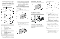
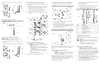
2. Insert the normally-open contact wiring into terminal block 4. Connecting the UPSs to the Bus Bar To connect the parallel input cord from each paralleled UPS to the Bus Bar in the rack: 1. Gently loop and twist the parallel input cords to minimize stress on the cords. The loop and twist for each cord might vary depending on configuration and strain relief. 2. Pull the cord retention bracket away from the Bus Bar (1). 3. Connect the parallel input cord to the Bus Bar (2). 4. Secure the parallel input cord by pushing in the cord retention bracket (3). Switching on the UPS input circuit breaker 1. Switch the UPS input circuit breaker on each UPS to the On position. • For the 8kVA models-Plug a PDU into the UPS output receptacle at the end of the power cord. • For the 12kVA models- a. Install the included output module on the rear rack frame. b. Plug the output module into the special UPS output receptacle, located on the rear of the UPS. Polarity for normally-open contacts Connecting to a normally-closed contact IMPORTANT: The remote switch must be in the closed position to enable power to the UPS output. 1. Remove the jumper from the normally-closed terminal block (connector 5). 2. Insert the normally-closed contact wiring into terminal block 5. Connecting the UPS to utility power WARNING: To prevent injury from electric shock or damage to the equipment: • Plug the input line cord into a grounded (earthed) electrical outlet that is installed near the equipment and is easily accessible. • Do not disable the grounding plug on the input line cord. The grounding plug is an important safety feature. • Do not use extension cords. Connect the UPS to a grounded utility power outlet. 2. Wait for the front panel display on each UPS to illuminate. The Alarm LED flashes on each UPS. 3. Check each UPS front panel display for active alarms or notices (other than "Batteries Disconnected"). Resolve any active alarms before continuing. For alarm troubleshooting, see "LED and audible alarm troubleshooting." Switching on the UPS battery circuit breaker When the UPS is plugged in and the battery circuit breaker is on, the UPS automatically enters Standby mode and begins charging the batteries. Connecting devices to the UPS CAUTION: Do not plug laser printers into the UPS output receptacles. The instantaneous current drawn by this type of printer can overload the UPS. Before connecting devices, verify that the UPS will not overload by checking that the ratings of the devices do not exceed the UPS capacity. If the equipment rating is listed in amps, multiply the number of amps by the nominal AC source to determine the VA. To provide additional receptacles: Item Description 1 Rack corner post 2 Mounting locations 3 Mounting top bracket 4 Output cord 5 Mounting bottom bracket 6 Input cord Charging the UPS batteries With the UPS in Standby mode, allow the batteries to charge before putting the UPS into service. IMPORTANT: Charge the batteries for at least 48 hours before supplying backup power to devices. The batteries charge to: • 80 percent of their capacity within 5 hours • 100 percent of their capacity within 48 hours Powering up the parallel system NOTE: Be sure that the total equipment ratings do not exceed the UPS capacity to prevent an overload alarm. 1. Be sure that the "Batteries Disconnected" alarm has cleared. Be sure that no other alarms appear on the UPS front panel display. If the Alarm LED is flashing, do not proceed until all alarms clear. Check the UPS status from the front panel to view the active alarms. Correct the alarms and restart if necessary. 2. On any UPS, press any button on the front panel display to activate the menu options, and then press the down arrow button until the TURN SYSTEM ON/OFF menu displays. 3. Press the down arrow button to display the TURN UPS ON option. Press the right arrow button.
-
 1
1 -
 2
2 -
 3
3 -
 4
4 -
 5
5
 |
 |
