HP RP36000/3 Adding an HP 3 Phase UPS to a parallel configuration Install Inst - Page 3
Connecting the REPO port
 |
View all HP RP36000/3 manuals
Add to My Manuals
Save this manual to your list of manuals |
Page 3 highlights
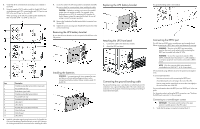
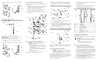
6. Verify that all the terminal blocks and jumpers are installed in each UPS. 7. Using the supplied CAT 5 cables, install the Parallel UPS Card wiring between each UPS, connecting the card OUT port on one UPS to the card IN port on the next UPS. When powering up the UPS, the parallel system identifies the UPS wired after UNIT 1 as UNIT 2, and so on. 9. Secure the cable to the UPS using cable ties and plastic standoffs. Be sure to check for correct polarity when installing the cable. CAUTION: If polarity or wiring is not correct, the parallel system does not operate normally. For example, when shutting down one UPS, the remaining UPS transfers the load to bypass instead of supporting the load. Be sure all wiring is correct for proper operation. 10. Remove the Standalone/Parallel terminal block connector from the top UPS. 11. Tighten the screws securing each Parallel UPS Card in the X-Slot communication bay. Removing the UPS battery bracket Be sure that all circuit breakers on the rear panel of the UPS are in the Off position. Replacing the UPS battery bracket Attaching the UPS front bezel 1. Connect the cable to the electronics module. 2. Attach the UPS front bezel. Item Description 1 Standalone/parallel terminal block (removed) 2 For parallel use only 3 Redundant signal cable 4 Standalone/parallel terminal block 5 For parallel use only 6 Standalone/parallel terminal block 7 UPS UNIT 1 8 UPS UNIT 2 9 Parallel UPS Card cable with ferrite 10 CAN OUT port 11 CAN IN port 12 UPS UNIT 3 8. Install the redundant signal wiring between the For Parallel Use Only and Standalone/Parallel terminals on each UPS. Remove the existing terminal block connectors before installing the cable. Installing the batteries WARNING: To prevent personal injury, prepare the area and observe all materials-handling procedures when transporting a battery module. Battery modules weigh 20 kg (44 lb). Connecting the ground bonding cable The ground bonding screw is provided as an attachment point for conductors. Use a ground bonding cable if the rack contains any conductors for the purpose of functional grounding or bonding of ungrounded metal parts. The ground bonding cable is not included. Connecting the REPO port This UPS has two REPO ports, normally-open and normally-closed. Before connecting to a REPO port, review and observe all warnings. WARNING: The pins on the REPO port are polarity sensitive. Be sure to verify polarity while connecting the REPO port in parallel with other HP UPSs. WARNING: To meet the requirements stated in NEC (NFPA 70) Articles 645-10 and 645-11, a UPS installed in a computer equipment room must be connected to a REPO circuit. NOTE: Wire the connector block using stranded, nonshielded wire (AWG #22 - #18, or equivalent). HP recommends using different colors for the positive and negative wires. To avoid inadvertant EPO: • Minimize wire strain while connecting the REPO port. • Avoid allowing the wires to hang in the rear of the UPS. • Use tie wraps and tie wrap blocks to secure the wires tightly to the rack and the rear of the UPS. For more information about the REPO port, see "REPO port" in the user guide. For information about verifying the REPO connection, see "Verifying the REPO port connection" in the user guide. Connecting to a normally-open contact IMPORTANT: The remote switch must be in the open position to enable power to the UPS output. 1. Verify that the jumper is inserted in terminal block 5.
-
 1
1 -
 2
2 -
 3
3 -
 4
4 -
 5
5
 |
 |
