HP Scitex FB10000 Geffen TS Error 66032 - Page 6
The B&R module is faulty
 |
View all HP Scitex FB10000 manuals
Add to My Manuals
Save this manual to your list of manuals |
Page 6 highlights
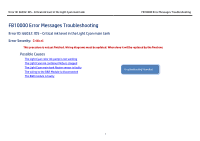
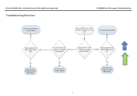
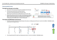
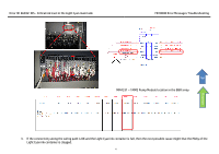
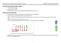
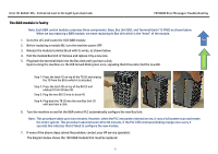
Error ID: 66032: IDS - Critical ink level in the Light Cyan main tank FB10000 Error Messages Troubleshooting The B&R module is faulty Note: Each B&R control module comprises three components: Base, Bus Unit (BU), and Terminal block (12 PINS) as shown below. When we say replacing a B&R module, we mean replacing its Bus Unit which is the "heart" of the module. 1. Go to the LEC and locate the 1DI3 B&R module Top 2. Before replacing a module BU, turn the machine power OFF. 3. Release the module terminal block with its wires, as shown below. 4. Pull the module Bus Unit of its base and replace it by a new one. 5. Plug back the terminal block into the Bus Unit until you hear a click. Upon turning the machine on, the R/E led will blink green once, signaling that it has detected the new BU. Flowchart Step 1: Press the latch (1) on top of the TB (2) and unplug the TB from the BU to which it is attached. Step 2: Press the latch (5) on top of the BU (3) and unplug it from its base (4). Step 3: Plug the new BU (3) into its base (4). Step 4: Plug back the TB (2) into the new Bus Unit (3) until you hear a click. 6. Turn the machine on and let the B&R control PLC automatically configure the new Bus Unit. Note: This procedure takes up to two minutes. However, when the PLC encounters internal errors, it runs a full system scan and resets the entire system. This procedure takes between 40 to 60 minutes. If the PLC LED continues blinking orange once every 5 seconds this indicates that it failed to configure the new module. 7. If none of the above steps solved the problem, contact your HP service specialist. The diagram below shows the 1DI3 B&R module that must be replaced. 6
-
 1
1 -
 2
2 -
 3
3 -
 4
4 -
 5
5 -
 6
6 -
 7
7 -
 8
8
 |
 |
