HP Scitex FB10000 Geffen TS Error 67003 - Page 5
Safety B&R Module is faulty
 |
View all HP Scitex FB10000 manuals
Add to My Manuals
Save this manual to your list of manuals |
Page 5 highlights
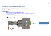
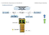
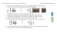
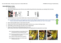
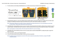
Error ID: 67003: Safety - Emergency stop pressed - Unloader (REC side) FB10000 Error Messages Troubleshooting Safety B&R Module is faulty 1. Turn the machine on. 2. Measure the voltage between each of the four wires and the 24V_gnd (24V_0) as shown below, you should get 24V in all 4 wires. Flowchart Top 3. If the error persists, this means that the B&R module is faulty and should be replaced. Note: Each B&R Safety module is comprised of three components: Base, BSU (Bus Supply Unit) module, and two (12 pins) Terminal blocks as shown below. Replacing a B&R module means replacing its BSU unit which is the "heart" of the module. 4. Before replacing a B&R module, turn the machine power OFF. 5. Release the two TBs from the faulty BSU module together with their wires, as shown in the figure below. 6. Pull the BSU out of the module base and replace it by a new BSU module. 7. Plug the two TBs back into the BSU module until you hear a click. Upon turning on the machine, the R/E led will blink green once, signaling that it has detected the new module. Step 1: Press the two latches (1) on top of the two TBs (2) and unplug them from the faulty BSU module. Step 2: Press the two latches (5) on top of the BSU module (3) and unplug it from its base (4). Step 3: Plug the new BSU module (3) into its base (4). Step 4: Plug the two TBs (2) back into the BSU module (3) until you hear a click. 5
-
 1
1 -
 2
2 -
 3
3 -
 4
4 -
 5
5 -
 6
6 -
 7
7
 |
 |
