HP Server rp7400 Hardware Manual - rp7400 - Page 155
Step 10., Replace the Back Top Cover, Step 11., Insert the SPU Back into the Cabinet
 |
View all HP Server rp7400 manuals
Add to My Manuals
Save this manual to your list of manuals |
Page 155 highlights
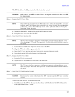
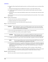
Add-On Memory c. Tighten the two captive screws at the support bridge. Step 10. Replace the Back Top Cover To replace the back top cover in the SPU: a. Angle the back edge of the top cover into the support bridge. Be sure the tabs at the back edge of the top cover insert into the slots on the support bridge. b. Lower the top cover onto the SPU. Firmly press the top cover down onto the SPU, making sure the outer edges of the top cover are over the top edges of the chassis. c. Tighten the two captive screws. Step 11. Insert the SPU Back into the Cabinet CAUTION Be aware of the cables at the back of the SPU while moving the SPU in or out of the cabinet. To insert the SPU into the cabinet from the back: a. Press the rail slide locks (one on each side) to release the rail locks while gently pushing the SPU forward. b. Carefully insert the SPU all the way into the cabinet until the front of the SPU sticks out approximately 2 to 4 inches. NOTE It is recommended that you push the SPU from the back of the cabinet. This allows you to monitor the cable movement to avoid snags and tangles with other SPUs or cables. c. Align the left and right bezel bracket key slots over the three bracket screws on each side of the SPU. d. Slide the bezel brackets down and tighten the six (three on each side) bracket screws. e. Carefully push the SPU back into the cabinet until the bezel brackets contact the cabinet vertical rails. f. Insert the four (two on each side, T25) SPU retainer screws, located just below and above bezel snap tabs. Check all cables to be sure none have been loosened during the previous procedure. Close or replace the rear door. 153
-
 1
1 -
2
-
3
-
4
-
5
-
6
-
7
-
8
-
9
-
10
-
11
-
12
-
13
-
14
-
15
-
16
-
17
-
18
-
19
-
20
-
21
-
22
-
23
-
24
-
25
-
26
-
27
-
28
-
29
-
30
-
31
-
32
-
33
-
34
-
35
-
36
-
37
-
38
-
39
-
40
-
41
-
42
-
43
-
44
-
45
-
46
-
47
-
48
-
49
-
50
-
51
-
52
-
53
-
54
-
55
-
56
-
57
-
58
-
59
-
60
-
61
-
62
-
63
-
64
-
65
-
66
-
67
-
68
-
69
-
70
-
71
-
72
-
73
-
74
-
75
-
76
-
77
-
78
-
79
-
80
-
81
-
82
-
83
-
84
-
85
-
86
-
87
-
88
-
89
-
90
-
91
-
92
-
93
-
94
-
95
-
96
-
97
-
98
-
99
-
100
-
101
-
102
-
103
-
104
-
105
-
106
-
107
-
108
-
109
-
110
-
111
-
112
-
113
-
114
-
115
-
116
-
117
-
118
-
119
-
120
-
121
-
122
-
123
-
124
-
125
-
126
-
127
-
128
-
129
-
130
-
131
-
132
-
133
-
134
-
135
-
136
-
137
-
138
-
139
-
140
-
141
-
142
-
143
-
144
-
145
-
146
-
147
-
148
-
149
-
 150
150 -
 151
151 -
 152
152 -
 153
153 -
 154
154 -
 155
155 -
 156
156 -
 157
157 -
 158
158 -
 159
159 -
 160
160 -
161
-
162
 |
 |