HP Server rp7400 Hardware Manual - rp7400 - Page 91
Unpacking Server, Bolts
 |
View all HP Server rp7400 manuals
Add to My Manuals
Save this manual to your list of manuals |
Page 91 highlights
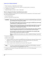
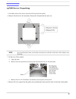
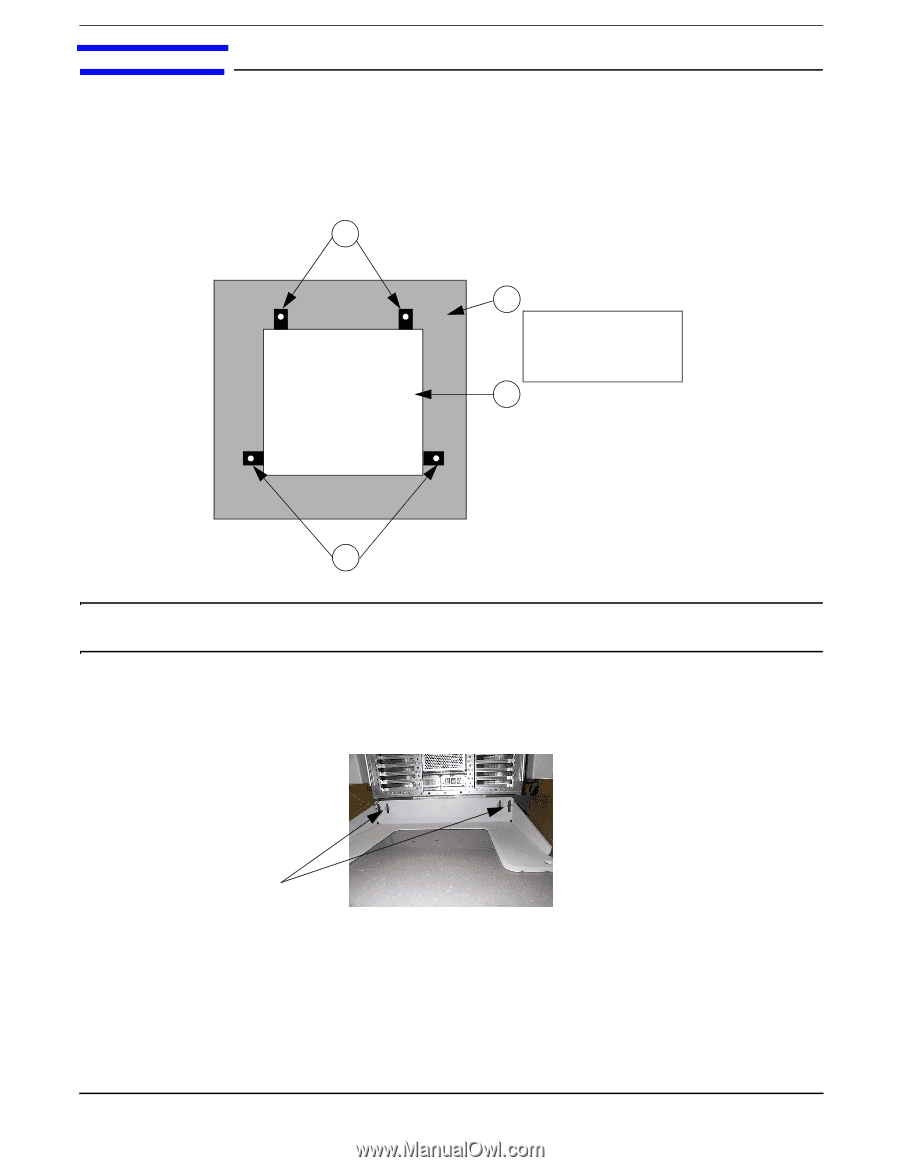
rp7400 Server Unpacking 1. Carefully remove the carton and anti-static bag from the pallet. 2. Remove the front two (2) L-brackets. Retain the 1/2-inch bolts for later use. 1 Rear 2 1. Shipping L-Bracket 2. Shipping Pallet 3 Front 1 NOTE As viewed from the front, one bracket is located on each side at the base of the cabinet near the front. 3. At the rear of the cabinet: a. Open the door. b. Remove the anti-tip foot by removing and retaining the two (2) 1/2-inch bolts. Bolts For Shipping: L-brackets are mounted behind anti-tip foot. Same bolts secure both. c. Remove the two (2) L-brackets (revealed by removing the anti-tip foot). 4. Remove the two ramps from the pallet and carefully place them into the slots at the front of the pallet. 91
-
 1
1 -
2
-
3
-
4
-
5
-
6
-
7
-
8
-
9
-
10
-
11
-
12
-
13
-
14
-
15
-
16
-
17
-
18
-
19
-
20
-
21
-
22
-
23
-
24
-
25
-
26
-
27
-
28
-
29
-
30
-
31
-
32
-
33
-
34
-
35
-
36
-
37
-
38
-
39
-
40
-
41
-
42
-
43
-
44
-
45
-
46
-
47
-
48
-
49
-
50
-
51
-
52
-
53
-
54
-
55
-
56
-
57
-
58
-
59
-
60
-
61
-
62
-
63
-
64
-
65
-
66
-
67
-
68
-
69
-
70
-
71
-
72
-
73
-
74
-
75
-
76
-
77
-
78
-
79
-
80
-
81
-
82
-
83
-
84
-
85
-
 86
86 -
 87
87 -
 88
88 -
 89
89 -
 90
90 -
 91
91 -
 92
92 -
 93
93 -
 94
94 -
 95
95 -
 96
96 -
97
-
98
-
99
-
100
-
101
-
102
-
103
-
104
-
105
-
106
-
107
-
108
-
109
-
110
-
111
-
112
-
113
-
114
-
115
-
116
-
117
-
118
-
119
-
120
-
121
-
122
-
123
-
124
-
125
-
126
-
127
-
128
-
129
-
130
-
131
-
132
-
133
-
134
-
135
-
136
-
137
-
138
-
139
-
140
-
141
-
142
-
143
-
144
-
145
-
146
-
147
-
148
-
149
-
150
-
151
-
152
-
153
-
154
-
155
-
156
-
157
-
158
-
159
-
160
-
161
-
162
 |
 |
91
rp7400 Server Unpacking
1. Carefully remove the carton and anti-static bag from the pallet.
2. Remove the front two (2) L-brackets. Retain the 1/2-inch bolts for later use.
NOTE
As viewed from the front, one bracket is located on each side at the base of the cabinet near
the front.
3. At the rear of the cabinet:
a.
Open the door.
b.
Remove the anti-tip foot by removing and retaining the two (2) 1/2-inch bolts.
c.
Remove the two (2) L-brackets (revealed by removing the anti-tip foot).
4. Remove the two ramps from the pallet and carefully place them into the slots at the front of the pallet.
Rear
Front
1
1
2
3
1. Shipping L-Bracket
2. Shipping Pallet
Bolts
For Shipping:
L-brackets are
mounted behind
anti-tip foot.
Same bolts
secure both.