HP Server rp8420 Installation Guide, Fifth Edition - HP 9000 rp8420 Server - Page 40
Top and Side Cover Removal and Installation, Removing the Top Cover, Cover Locations
 |
View all HP Server rp8420 manuals
Add to My Manuals
Save this manual to your list of manuals |
Page 40 highlights
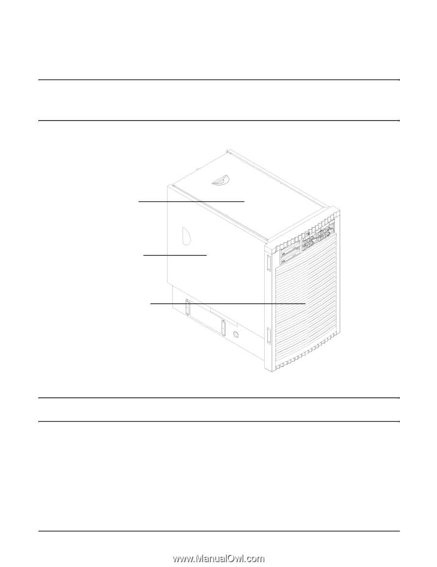
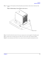
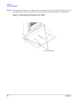
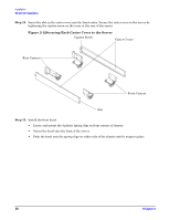
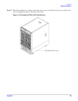
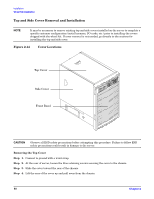
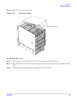
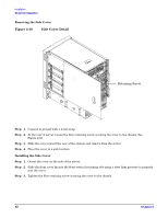
Installation Wheel Kit Installation Top and Side Cover Removal and Installation NOTE It may be necessary to remove existing top and side covers installed on the server to complete a specific customer configuration (install memory, I/O cards, etc.) prior to installing the covers shipped with the wheel kit. If cover removal is not needed, go directly to the sections for installing the top and side cover. Figure 2-14 Cover Locations Top Cover Side Cover Front Bezel CAUTION Observe all ESD safety precautions before attempting this procedure. Failure to follow ESD safety precautions could result in damage to the server. Removing the Top Cover Step 1. Connect to ground with a wrist strap. Step 2. At the rear of server, loosen the blue retaining screws securing the cover to the chassis. Step 3. Slide the cover toward the rear of the chassis. Step 4. Lift the rear of the cover up and pull away from the chassis. 40 Chapter 2
-
 1
1 -
2
-
3
-
4
-
5
-
6
-
7
-
8
-
9
-
10
-
11
-
12
-
13
-
14
-
15
-
16
-
17
-
18
-
19
-
20
-
21
-
22
-
23
-
24
-
25
-
26
-
27
-
28
-
29
-
30
-
31
-
32
-
33
-
34
-
 35
35 -
 36
36 -
 37
37 -
 38
38 -
 39
39 -
 40
40 -
 41
41 -
 42
42 -
 43
43 -
 44
44 -
 45
45 -
46
-
47
-
48
-
49
-
50
-
51
-
52
-
53
-
54
-
55
-
56
-
57
-
58
-
59
-
60
-
61
-
62
-
63
-
64
-
65
-
66
-
67
-
68
-
69
-
70
-
71
-
72
-
73
-
74
-
75
-
76
-
77
-
78
-
79
-
80
 |
 |