HP Server rp8420 Installation Guide, Fifth Edition - HP 9000 rp8420 Server - Page 70
Verifying Presence of the Cell Boards, Configuring AC Line Status, The du Command Screen
 |
View all HP Server rp8420 manuals
Add to My Manuals
Save this manual to your list of manuals |
Page 70 highlights
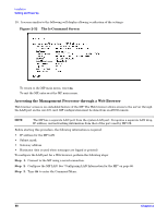
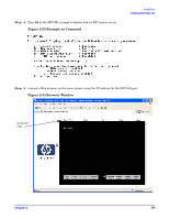
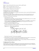
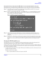
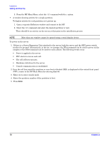
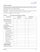
Installation Cabling and Power Up Step 6. Click on the Zoom In/Out tab to generate a full screen MP window. Step 7. Select the emulation type you want to use. Step 8. Login to the MP when the login window appears. Access to the MP via a Web browser is now possible. Verifying Presence of the Cell Boards To perform this activity, either connect to the MP over the customer console or connect the CE Tool (laptop) to the RS-232 Local port on the MP. After logging in to the MP, verify that the MP detects the presence of all the cells installed in the server cabinet. It is important for the MP to detect the cell boards. If it does not, the partitions will not boot. To determine if the MP detects the cell boards: 1. At the MP prompt, enter cm. This displays the Command Menu. Among other things, the Command Menu allows one to view or modify the configuration and look at utilities controlled by the MP. To look at a list of the commands available, enter he. You might have to press Enter to see more than one screen of commands. Use the Page Up and Page Down keys to view the previous or next screen of commands. To exit the Help Menu, enter q. 2. From the command prompt (MP:CM>), enter du. The du command displays the MP Bus topology. A screen similar to the following is displayed: Figure 2-35 The du Command Screen There will be an asterisk (*) in the column marked MP. 3. Verify that there is an asterisk (*) for each of the cells installed in the server cabinet, by comparing what is in the Cells column with the cells physically located inside the server cabinet. Figure 2-35 shows that cells are installed in slots 0, 1, 2, and 3 in cabinet 0. In the server cabinet, there should be cells physically located in slots 0, 1, 2, and 3. Configuring AC Line Status The MP utilities can detect if power is applied to each of the AC input cords for the server, by sampling the status of the bulk power supplies. During installation, use the following procedure to check the configuration for the AC line status and configure it to match the customer's environment. 70 Chapter 2
-
 1
1 -
2
-
3
-
4
-
5
-
6
-
7
-
8
-
9
-
10
-
11
-
12
-
13
-
14
-
15
-
16
-
17
-
18
-
19
-
20
-
21
-
22
-
23
-
24
-
25
-
26
-
27
-
28
-
29
-
30
-
31
-
32
-
33
-
34
-
35
-
36
-
37
-
38
-
39
-
40
-
41
-
42
-
43
-
44
-
45
-
46
-
47
-
48
-
49
-
50
-
51
-
52
-
53
-
54
-
55
-
56
-
57
-
58
-
59
-
60
-
61
-
62
-
63
-
64
-
 65
65 -
 66
66 -
 67
67 -
 68
68 -
 69
69 -
 70
70 -
 71
71 -
 72
72 -
 73
73 -
 74
74 -
 75
75 -
76
-
77
-
78
-
79
-
80
 |
 |