HP Server rp8420 Installation Guide, Fifth Edition - HP 9000 rp8420 Server - Page 9

s, LAN and RS-232 Connectors on the Core I/O Board .62

Page 9 highlights

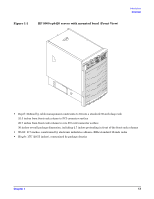
Figures Figure 1-1. HP 9000 rp8420 server with mounted bezel (Front View 13 Figure 1-2. HP 9000 rp8420 server with bezel removed (Front View 15 Figure 1-3. HP 9000 rp8420 server with top cover removed (Rear View 16 Figure 1-4. Front Panel LEDs and Power Switch 17 Figure 1-5. Internal Disks 19 Figure 2-1. Removing the Polystraps and Cardboard 23 Figure 2-2. Removing the Shipping Bolts and Plastic Cover 24 Figure 2-3. Preparing to Roll Off the Pallet 25 Figure 2-4. Securing the Cabinet 26 Figure 2-5. Positioning the Lifter to the Pallet 30 Figure 2-6. Raising the Server off the Pallet Cushions 31 Figure 2-7. Server on Shipping Pallet 33 Figure 2-8. Removal of Cushion from Front Edge of Server 34 Figure 2-9. Attaching a Caster Wheel to the Server 35 Figure 2-10. Attaching the Ramp to the Pallet 36 Figure 2-11. Side Cushion Removal from Server 37 Figure 2-12. Securing Each Caster Cover to the Server 38 Figure 2-13. Completed Wheel Kit Installation 39 Figure 2-14. Cover Locations 40 Figure 2-15. Top Cover Detail 41 Figure 2-16. Side Cover Detail 42 Figure 2-17. Embedded Disks 44 Figure 2-18. PCI I/O Slot Details 49 Figure 2-19. Voltage Reference Points for IEC-320 C19 Plug 51 Figure 2-20. Safety Ground Reference Check-Single Power Source 52 Figure 2-21. Safety Ground Reference Check-Dual Power Source 53 Figure 2-22. Wall Receptacle Pinouts 54 Figure 2-23. AC Power Input Labeling 55 Figure 2-24. Distribution of Input Power for Each BPS 56 Figure 2-25. Four Cell Line Cord Anchor (rp8400, rp8420, rp8440, rx8620, rx8640 58 Figure 2-26. Line Cord Anchor and Velcro Straps 59 Figure 2-27. LAN and RS-232 Connectors on the Core I/O Board 62 Figure 2-28. Front Panel Display 63 Figure 2-29. BPS LED Location 64 Figure 2-30. MP Main Menu 65 Figure 2-31. The lc Command Screen 66 Figure 2-32. The ls Command Screen 67 Figure 2-33. Example sa Command 68 Figure 2-34. Browser Window 69 Figure 2-35. The du Command Screen 70 Figure 2-36. The pwrgrd Command Screen 71 9

  • 1
  • 2
  • 3
  • 4
  • 5
  • 6
  • 7
  • 8
  • 9
  • 10
  • 11
  • 12
  • 13
  • 14
  • 15
  • 16
  • 17
  • 18
  • 19
  • 20
  • 21
  • 22
  • 23
  • 24
  • 25
  • 26
  • 27
  • 28
  • 29
  • 30
  • 31
  • 32
  • 33
  • 34
  • 35
  • 36
  • 37
  • 38
  • 39
  • 40
  • 41
  • 42
  • 43
  • 44
  • 45
  • 46
  • 47
  • 48
  • 49
  • 50
  • 51
  • 52
  • 53
  • 54
  • 55
  • 56
  • 57
  • 58
  • 59
  • 60
  • 61
  • 62
  • 63
  • 64
  • 65
  • 66
  • 67
  • 68
  • 69
  • 70
  • 71
  • 72
  • 73
  • 74
  • 75
  • 76
  • 77
  • 78
  • 79
  • 80

Figures
9
Figure 1-1. HP 9000 rp8420 server with mounted bezel (Front View) . . . . . . . . . . . . . . . . . . . . . . . 13
Figure 1-2. HP 9000 rp8420 server with bezel removed (Front View) . . . . . . . . . . . . . . . . . . . . . . . 15
Figure 1-3. HP 9000 rp8420 server with top cover removed (Rear View). . . . . . . . . . . . . . . . . . . . . 16
Figure 1-4. Front Panel LEDs and Power Switch . . . . . . . . . . . . . . . . . . . . . . . . . . . . . . . . . . . . . . . 17
Figure 1-5. Internal Disks . . . . . . . . . . . . . . . . . . . . . . . . . . . . . . . . . . . . . . . . . . . . . . . . . . . . . . . . . . 19
Figure 2-1.
Removing the Polystraps and Cardboard . . . . . . . . . . . . . . . . . . . . . . . . . . . . . . . . . . . . 23
Figure 2-2.
Removing the Shipping Bolts and Plastic Cover . . . . . . . . . . . . . . . . . . . . . . . . . . . . . . 24
Figure 2-3.
Preparing to Roll Off the Pallet. . . . . . . . . . . . . . . . . . . . . . . . . . . . . . . . . . . . . . . . . . . . 25
Figure 2-4. Securing the Cabinet . . . . . . . . . . . . . . . . . . . . . . . . . . . . . . . . . . . . . . . . . . . . . . . . . . . . 26
Figure 2-5.
Positioning the Lifter to the Pallet . . . . . . . . . . . . . . . . . . . . . . . . . . . . . . . . . . . . . . . . . 30
Figure 2-6.
Raising the Server off the Pallet Cushions. . . . . . . . . . . . . . . . . . . . . . . . . . . . . . . . . . . 31
Figure 2-7. Server on Shipping Pallet. . . . . . . . . . . . . . . . . . . . . . . . . . . . . . . . . . . . . . . . . . . . . . . . . 33
Figure 2-8. Removal of Cushion from Front Edge of Server . . . . . . . . . . . . . . . . . . . . . . . . . . . . . . . 34
Figure 2-9. Attaching a Caster Wheel to the Server . . . . . . . . . . . . . . . . . . . . . . . . . . . . . . . . . . . . . 35
Figure 2-10. Attaching the Ramp to the Pallet. . . . . . . . . . . . . . . . . . . . . . . . . . . . . . . . . . . . . . . . . . 36
Figure 2-11. Side Cushion Removal from Server . . . . . . . . . . . . . . . . . . . . . . . . . . . . . . . . . . . . . . . . 37
Figure 2-12. Securing Each Caster Cover to the Server . . . . . . . . . . . . . . . . . . . . . . . . . . . . . . . . . . 38
Figure 2-13. Completed Wheel Kit Installation . . . . . . . . . . . . . . . . . . . . . . . . . . . . . . . . . . . . . . . . . 39
Figure 2-14. Cover Locations. . . . . . . . . . . . . . . . . . . . . . . . . . . . . . . . . . . . . . . . . . . . . . . . . . . . . . . . 40
Figure 2-15. Top Cover Detail . . . . . . . . . . . . . . . . . . . . . . . . . . . . . . . . . . . . . . . . . . . . . . . . . . . . . . . 41
Figure 2-16. Side Cover Detail . . . . . . . . . . . . . . . . . . . . . . . . . . . . . . . . . . . . . . . . . . . . . . . . . . . . . . 42
Figure 2-17. Embedded Disks . . . . . . . . . . . . . . . . . . . . . . . . . . . . . . . . . . . . . . . . . . . . . . . . . . . . . . . 44
Figure 2-18.
PCI I/O Slot Details . . . . . . . . . . . . . . . . . . . . . . . . . . . . . . . . . . . . . . . . . . . . . . . . . . . . 49
Figure 2-19.
Voltage Reference Points for IEC-320 C19 Plug. . . . . . . . . . . . . . . . . . . . . . . . . . . . . . 51
Figure 2-20.
Safety Ground Reference Check—Single Power Source . . . . . . . . . . . . . . . . . . . . . . . 52
Figure 2-21.
Safety Ground Reference Check—Dual Power Source . . . . . . . . . . . . . . . . . . . . . . . . 53
Figure 2-22.
Wall Receptacle Pinouts. . . . . . . . . . . . . . . . . . . . . . . . . . . . . . . . . . . . . . . . . . . . . . . . . 54
Figure 2-23. AC Power Input Labeling . . . . . . . . . . . . . . . . . . . . . . . . . . . . . . . . . . . . . . . . . . . . . . . . 55
Figure 2-24. Distribution of Input Power for Each BPS . . . . . . . . . . . . . . . . . . . . . . . . . . . . . . . . . . 56
Figure 2-25. Four Cell Line Cord Anchor (rp8400, rp8420, rp8440, rx8620, rx8640) . . . . . . . . . . . 58
Figure 2-26. Line Cord Anchor and Velcro Straps . . . . . . . . . . . . . . . . . . . . . . . . . . . . . . . . . . . . . . . 59
Figure 2-27. LAN and RS-232 Connectors on the Core I/O Board . . . . . . . . . . . . . . . . . . . . . . . . . . 62
Figure 2-28. Front Panel Display . . . . . . . . . . . . . . . . . . . . . . . . . . . . . . . . . . . . . . . . . . . . . . . . . . . . 63
Figure 2-29. BPS LED Location . . . . . . . . . . . . . . . . . . . . . . . . . . . . . . . . . . . . . . . . . . . . . . . . . . . . . 64
Figure 2-30.
MP Main Menu . . . . . . . . . . . . . . . . . . . . . . . . . . . . . . . . . . . . . . . . . . . . . . . . . . . . . . . 65
Figure 2-31. The lc Command Screen . . . . . . . . . . . . . . . . . . . . . . . . . . . . . . . . . . . . . . . . . . . . . . . . . 66
Figure 2-32. The ls Command Screen . . . . . . . . . . . . . . . . . . . . . . . . . . . . . . . . . . . . . . . . . . . . . . . . . 67
Figure 2-33.
Example sa Command . . . . . . . . . . . . . . . . . . . . . . . . . . . . . . . . . . . . . . . . . . . . . . . . . . 68
Figure 2-34.
Browser Window . . . . . . . . . . . . . . . . . . . . . . . . . . . . . . . . . . . . . . . . . . . . . . . . . . . . . . 69
Figure 2-35. The du Command Screen . . . . . . . . . . . . . . . . . . . . . . . . . . . . . . . . . . . . . . . . . . . . . . . . 70
Figure 2-36.
The pwrgrd Command Screen. . . . . . . . . . . . . . . . . . . . . . . . . . . . . . . . . . . . . . . . . . . . 71