HP Spectre 15-bl000 Maintenance and Service Guide - Page 33
WLAN module, CAUTION
 |
View all HP Spectre 15-bl000 manuals
Add to My Manuals
Save this manual to your list of manuals |
Page 33 highlights
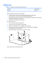
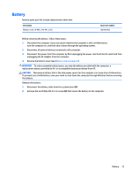
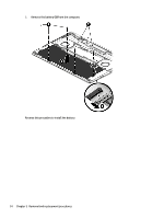
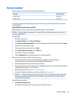
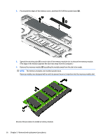
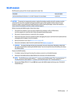
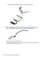
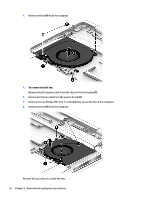
WLAN module WLAN module spare part kits include replacement rubber feet. Description Intel Dual Band Wireless-AC 8265 802.11 ac 2×2 WiFi + Bluetooth 4.2 Combo Adapter Spare part number 910264-856 CAUTION: To prevent an unresponsive system, replace the wireless module only with a wireless module authorized for use in the computer by the governmental agency that regulates wireless devices in your country or region. If you replace the module and then receive a warning message, remove the module to restore device functionality, and then contact technical support. Before removing the WLAN module, follow these steps: 1. Shut down the computer. If you are unsure whether the computer is off or in Hibernation, turn the computer on, and then shut it down through the operating system. 2. Disconnect all external devices connected to the computer. 3. Disconnect the power from the computer by first unplugging the power cord from the AC outlet and then unplugging the AC adapter from the computer. 4. Remove the bottom cover (see Bottom cover on page 22). 5. Disconnect the battery cable from the system board (see Battery on page 23). CAUTION: To prevent damage to internal components, be sure to disconnect the battery cable from the system board before removing the WLAN module. You do not need to remove the battery to remove the WLAN module. Remove the WLAN module: 1. If installed, remove the tape from atop the antenna connectors on the WLAN module. 2. Disconnect the WLAN antenna cables (1) from the terminals on the WLAN module. NOTE: The WLAN antenna cable labeled "1" connects to the WLAN module "Main" terminal labeled "1". The WLAN antenna cable labeled "2" connects to the WLAN module "Aux" terminal labeled "2". 3. Remove the Phillips PM2.0×2.7 screw (2) that secures the WLAN module to the top cover. (The WLAN module tilts up.) WLAN module 27
-
 1
1 -
2
-
3
-
4
-
5
-
6
-
7
-
8
-
9
-
10
-
11
-
12
-
13
-
14
-
15
-
16
-
17
-
18
-
19
-
20
-
21
-
22
-
23
-
24
-
25
-
26
-
27
-
 28
28 -
 29
29 -
 30
30 -
 31
31 -
 32
32 -
 33
33 -
 34
34 -
 35
35 -
 36
36 -
 37
37 -
 38
38 -
39
-
40
-
41
-
42
-
43
-
44
-
45
-
46
-
47
-
48
-
49
-
50
-
51
-
52
-
53
-
54
-
55
-
56
-
57
-
58
-
59
-
60
-
61
-
62
-
63
-
64
-
65
-
66
-
67
-
68
-
69
-
70
-
71
-
72
-
73
-
74
 |
 |
