HP Spectre x360 Spectre x360 Convertible PC model numbers 13-4000 through 4099 - Page 39
Remove the Phillips PM2.0×2.7 screw, module tilts up.
 |
View all HP Spectre x360 manuals
Add to My Manuals
Save this manual to your list of manuals |
Page 39 highlights
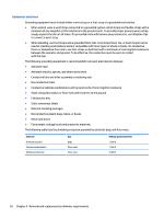
3. Disconnect the power from the computer by first unplugging the power cord from the AC outlet and then unplugging the AC adapter from the computer. 4. Remove the bottom cover (see Bottom cover on page 28). 5. Disconnect the battery cable from the system board (see Battery on page 29). Remove the WLAN module: 1. Disconnect the WLAN antenna cables (1) from the terminals on the WLAN module. NOTE: The WLAN antenna cable labeled "1" connects to the WLAN module "Main" terminal labeled "1". The WLAN antenna cable labeled "2" connects to the WLAN module "Aux" terminal labeled "2". 2. Remove the Phillips PM2.0×2.7 screw (2) that secures the WLAN module to the top cover. (The WLAN module tilts up.) 3. Remove the WLAN module (3) by pulling the module away from the slot at an angle. NOTE: If the WLAN antenna cables are not connected to the terminals on the WLAN module, protective sleeves should be installed on the antenna connectors, as shown in the following illustration. WLAN module 31
-
 1
1 -
2
-
3
-
4
-
5
-
6
-
7
-
8
-
9
-
10
-
11
-
12
-
13
-
14
-
15
-
16
-
17
-
18
-
19
-
20
-
21
-
22
-
23
-
24
-
25
-
26
-
27
-
28
-
29
-
30
-
31
-
32
-
33
-
 34
34 -
 35
35 -
 36
36 -
 37
37 -
 38
38 -
 39
39 -
 40
40 -
 41
41 -
 42
42 -
 43
43 -
 44
44 -
45
-
46
-
47
-
48
-
49
-
50
-
51
-
52
-
53
-
54
-
55
-
56
-
57
-
58
-
59
-
60
-
61
-
62
-
63
-
64
-
65
-
66
-
67
-
68
-
69
-
70
-
71
-
72
-
73
-
74
-
75
-
76
-
77
-
78
-
79
-
80
-
81
-
82
-
83
-
84
-
85
-
86
-
87
-
88
-
89
-
90
-
91
-
92
-
93
-
94
-
95
-
96
-
97
-
98
-
99
-
100
 |
 |
