HP StorageWorks 2500 HP StorageWorks 2500 Disk System User Guide (5697-5922, N - Page 83
Voltage sensor and current sensor error conditions, Transceiver element numbers
 |
View all HP StorageWorks 2500 manuals
Add to My Manuals
Save this manual to your list of manuals |
Page 83 highlights
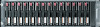
4 2 3 1 CXO7461A 1. Transceiver 01 2. Transceiver 02 3. Transceiver 03 4. Transceiver 04 Figure 37 Transceiver element numbers Table 27 Transceiver error conditions Error condition code Severity Description Actions 0.F.en.01 Critical Transceiver en is incompatible with the I/O module. Contact your HP-authorized service representative. 0.F.en.02 Critical Transceiver en can not detect a data signal. 0.F.en.03 Critical Fibre Channel DS2500 bus fault involving transceiver en 0.F.en.04 Critical The EMU detects that transceiver en has Install a new transceiver. been removed. 0.F.en.05 Critical An invalid Fibre Channel character was detected in the incoming data stream on transceiver en. Contact your HP-authorized service representative. Voltage sensor and current sensor error conditions The format of a sensor error condition reports is 1.2.en.ec for a voltage sensor, and 1.3.en.ec for a current sensor, where: • 1.2. identifies a voltage sensor error. • 1.3.identifies a current sensor error. • en. identifies the location of the affected sensor (see Table 28). When viewed from the rear of the enclosure, power supply 1 is on the left, and power supply 2 is on the right. • ec is the error code. 2500 Disk System user guide 83
-
 1
1 -
2
-
3
-
4
-
5
-
6
-
7
-
8
-
9
-
10
-
11
-
12
-
13
-
14
-
15
-
16
-
17
-
18
-
19
-
20
-
21
-
22
-
23
-
24
-
25
-
26
-
27
-
28
-
29
-
30
-
31
-
32
-
33
-
34
-
35
-
36
-
37
-
38
-
39
-
40
-
41
-
42
-
43
-
44
-
45
-
46
-
47
-
48
-
49
-
50
-
51
-
52
-
53
-
54
-
55
-
56
-
57
-
58
-
59
-
60
-
61
-
62
-
63
-
64
-
65
-
66
-
67
-
68
-
69
-
70
-
71
-
72
-
73
-
74
-
75
-
76
-
77
-
 78
78 -
 79
79 -
 80
80 -
 81
81 -
 82
82 -
 83
83 -
 84
84 -
 85
85 -
 86
86 -
 87
87 -
 88
88 -
89
 |
 |
