HP StorageWorks MSA2312fc HP StorageWorks 2312fc and 2324fc Modular Smart Arra - Page 22
Connecting controller and MSA2000 3.5 12-drive enclosures
 |
View all HP StorageWorks MSA2312fc manuals
Add to My Manuals
Save this manual to your list of manuals |
Page 22 highlights
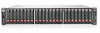
Connecting controller and MSA2000 3.5 12-drive enclosures You can connect up to four MSA2000 3.5 12-drive enclosures to an MSA2312fc and up to three MSA2000 3.5 12-drive enclosures to an MSA2324fc. The cabling diagrams shown in this section show the recommended fault-tolerant cabling patterns. IMPORTANT: Connecting an MSA2000 3.5 12-drive enclosure to an MSA2312fc or MSA2324fc requires mini SAS to SAS cables. IMPORTANT: Adding a fourth drive enclosure to an MSA2312fc may require a separate, longer cable. Check the QuickSpecs for an updated list of supported cables. QuickSpecs can be found from your HP MSA products page at http://www.hp.com/go/msa. Select MSA SAN Arrays, and then select your product. The link for QuickSpecs will be on the right. IMPORTANT: The MSA2324fc can also be attached to an MSA70 that is running firmware version 2.18 or later. For information about the MSA70, see the HP StorageWorks 70 Modular Smart Array Enclosure user guide located on the MSA2000 Software Support/Documentation CD shipped with your product or at http://hp.com/support/manuals. When connecting multiple drive enclosures, use reverse cabling to ensure the highest level of fault tolerance. Controllers and I/O (expansion) modules are identified by . For example, Figure 3 shows controller 1A connected to I/O module 2A, and the chain of connections continuing down. Controller 1B is connected to the lower module (B) of the last drive enclosure in the chain, with connections moving in the opposite direction. NOTE: For clarity, the schematic illustrations of the controllers shown in this section show only relevant details such as expansion ports. For detailed illustrations showing all components, see Rear panel components. 1A 1B In Out 2A 2B Figure 1 Cabling connections between a single-controller enclosure and one MSA2000 3.5 12-drive enclosure 22 Installing the enclosures
-
 1
1 -
2
-
3
-
4
-
5
-
6
-
7
-
8
-
9
-
10
-
11
-
12
-
13
-
14
-
15
-
16
-
 17
17 -
 18
18 -
 19
19 -
 20
20 -
 21
21 -
 22
22 -
 23
23 -
 24
24 -
 25
25 -
 26
26 -
 27
27 -
28
-
29
-
30
-
31
-
32
-
33
-
34
-
35
-
36
-
37
-
38
-
39
-
40
-
41
-
42
-
43
-
44
-
45
-
46
-
47
-
48
-
49
-
50
-
51
-
52
-
53
-
54
-
55
-
56
-
57
-
58
-
59
-
60
-
61
-
62
-
63
-
64
-
65
-
66
-
67
-
68
-
69
-
70
-
71
-
72
-
73
-
74
-
75
-
76
 |
 |
