HP StorageWorks P2000 HP StorageWorks P2000 G3 MSA System FC User Guide (59033 - Page 37
Setting Network port IP addresses using the CLI, Management Port IP Address, IP Subnet Mask - msa usb driver
 |
View all HP StorageWorks P2000 manuals
Add to My Manuals
Save this manual to your list of manuals |
Page 37 highlights
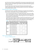
Setting Network port IP addresses using the CLI If you did not use the MSA Device Discovery Tool to set network port IP values, set them manually (alternative method) as described below. NOTE: Check the HP MSA downloads page at http://www.hp.com/support/downloads for relevant download drivers and software. Network ports on controller module A and controller module B are configured with the following default values: • Management Port IP Address: 10.0.0.2 (controller A), 10.0.0.3 (controller B) • IP Subnet Mask: 255.255.255.0 • Gateway IP Address: 10.0.0.1 If the default IP addresses are not compatible with your network, you must set an IP address for each network port using the command-line interface (CLI) embedded in each controller module. The CLI enables you to access the system using the USB (universal serial bus) communication interface and terminal emulation software. The USB cable and CLI port support USB version 2.0. Use the CLI commands described in the steps below to set the IP address for the Network port on each controller module. Once new IP addresses are set, you can change them as needed using SMU. Be sure to change the IP address via SMU before changing the network configuration. NOTE: Changing IP settings can cause management hosts to lose access to the storage system. 1. From your network administrator, obtain an IP address, subnet mask, and gateway address for controller A and controller B. 2. Use the provided USB cable to connect controller A to a USB port on a host computer. The USB mini 5 male connector plugs into the CLI port as shown in Figure 14 (generic controller module is shown). Host Not SInhtoewrfance Host Not SInhtoewrfance CLI CLI HOST LINK Service ACT DIRTY CACHE CLI ACTIVITY LINK Connect USB cable to CLI port on controller faceplate Figure 14 Connecting a USB cable to the CLI port 3. Start and configure a terminal emulator, such as HyperTerminal or VT-100, using the display settings in Table 5 on page 38 and the connection settings in Table 6 on page 38. HP StorageWorks P2000 G3 MSA System FC User Guide 37
-
 1
1 -
2
-
3
-
4
-
5
-
6
-
7
-
8
-
9
-
10
-
11
-
12
-
13
-
14
-
15
-
16
-
17
-
18
-
19
-
20
-
21
-
22
-
23
-
24
-
25
-
26
-
27
-
28
-
29
-
30
-
31
-
 32
32 -
 33
33 -
 34
34 -
 35
35 -
 36
36 -
 37
37 -
 38
38 -
 39
39 -
 40
40 -
 41
41 -
 42
42 -
43
-
44
-
45
-
46
-
47
-
48
-
49
-
50
-
51
-
52
-
53
-
54
-
55
-
56
-
57
-
58
-
59
-
60
-
61
-
62
-
63
-
64
-
65
-
66
-
67
-
68
-
69
-
70
-
71
-
72
-
73
-
74
 |
 |