HP StorageWorks P2000 HP StorageWorks P2000 G3 MSA System FC/iSCSI User Guide - Page 28
Cabling connections between P2000 G3 MSA System controllers and P2000 6Gb drive, - g3 schematic
 |
View all HP StorageWorks P2000 manuals
Add to My Manuals
Save this manual to your list of manuals |
Page 28 highlights
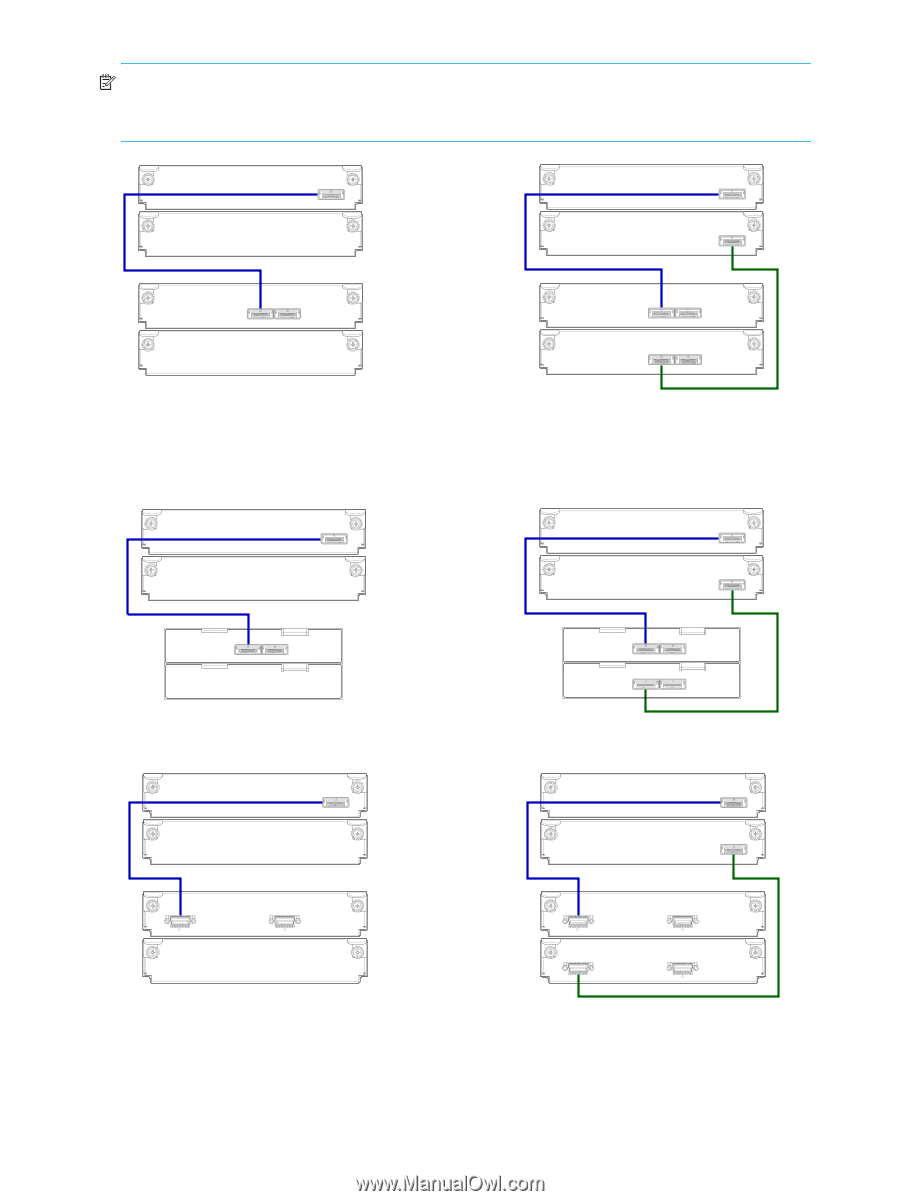
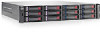
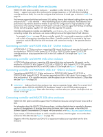
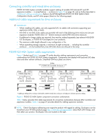
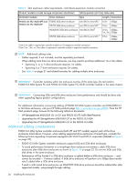
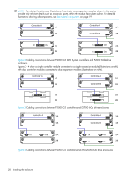
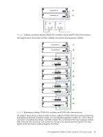
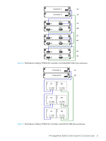
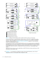
NOTE: For clarity, the schematic illustrations of controller and expansion modules shown in this section provide only relevant details such as expansion ports within the module face plate outline. For detailed illustrations showing all components, see Rear panel components on page 19. Controller A 1A 1B Controller A 1A Controller B 1B In Out 2A 2B In Out 2A In Out 2B Figure 2 Cabling connections between P2000 G3 MSA System controllers and P2000 6Gb drive enclosures Figures 2 - 4 show a single controller module connected to a single expansion module (illustrations on left), with dual controller modules connected to dual expansion modules (illustrations on right). Controller A 1A Controller A 1A 1B Controller B 1B P1 P2 2A 2B P1 P2 2A P1 P2 2B Figure 3 Cabling connections between P2000 G3 controllers and D2700 6Gb drive enclosures Controller A 1A 1B Controller A 1A Controller B 1B In Out 2A 2B In Out 2A In Out 2B Figure 4 Cabling connections between P2000 G3 controllers and MSA2000 3Gb drive enclosures 28 Installing the enclosures
-
 1
1 -
2
-
3
-
4
-
5
-
6
-
7
-
8
-
9
-
10
-
11
-
12
-
13
-
14
-
15
-
16
-
17
-
18
-
19
-
20
-
21
-
22
-
 23
23 -
 24
24 -
 25
25 -
 26
26 -
 27
27 -
 28
28 -
 29
29 -
 30
30 -
 31
31 -
 32
32 -
 33
33 -
34
-
35
-
36
-
37
-
38
-
39
-
40
-
41
-
42
-
43
-
44
-
45
-
46
-
47
-
48
-
49
-
50
-
51
-
52
-
53
-
54
-
55
-
56
-
57
-
58
-
59
-
60
-
61
-
62
-
63
-
64
-
65
-
66
-
67
-
68
-
69
-
70
-
71
-
72
-
73
-
74
-
75
-
76
-
77
-
78
 |
 |