HP Stream Notebook - 11-d010wm HP Stream Notebook PC (model numbers 11-d000 th - Page 48
Power connector cable, and routing channel built into
 |
View all HP Stream Notebook - 11-d010wm manuals
Add to My Manuals
Save this manual to your list of manuals |
Page 48 highlights
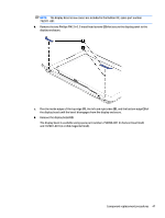
Power connector cable Description Power connector cable Spare part number 787922-001 Before removing the power connector cable, follow these steps: 1. Turn off the computer. If you are unsure whether the computer is off or in Hibernation, turn the computer on, and then shut it down through the operating system. 2. Disconnect the power from the computer by unplugging the power cord from the computer. 3. Disconnect all external devices from the computer. 4. Remove the keyboard/top cover (see Keyboard/top cover on page 28). Remove the power connector cable: 1. Disconnect the power connector cable (1) from the system board. 2. Release the power connector cable from the retention clips (2) and routing channel built into the base enclosure. 3. Release the power connector from the retention molding (3) built into the base enclosure. 4. Remove the power connector cable. Reverse this procedure to install the power connector cable. 42 Chapter 5 Removal and replacement procedures
-
 1
1 -
2
-
3
-
4
-
5
-
6
-
7
-
8
-
9
-
10
-
11
-
12
-
13
-
14
-
15
-
16
-
17
-
18
-
19
-
20
-
21
-
22
-
23
-
24
-
25
-
26
-
27
-
28
-
29
-
30
-
31
-
32
-
33
-
34
-
35
-
36
-
37
-
38
-
39
-
40
-
41
-
42
-
 43
43 -
 44
44 -
 45
45 -
 46
46 -
 47
47 -
 48
48 -
 49
49 -
 50
50 -
 51
51 -
 52
52 -
 53
53 -
54
-
55
-
56
-
57
-
58
-
59
-
60
-
61
-
62
-
63
-
64
-
65
-
66
-
67
-
68
-
69
-
70
-
71
-
72
-
73
 |
 |
