HP T5530 Troubleshooting Guide for HP t5135 and t5530 Thin Client - Page 80
Replace the two screws that secure the access panel to the chassis 3.
 |
UPC - 882780773684
View all HP T5530 manuals
Add to My Manuals
Save this manual to your list of manuals |
Page 80 highlights
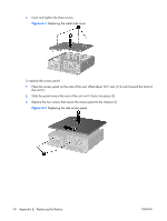
2. Insert and tighten the three screws. Figure E-4 Replacing the metal side cover To replace the access panel: 1. Place the access panel on the side of the unit, offset about 12.7-mm (1/2-inch) toward the front of the unit (1). 2. Slide the panel toward the rear of the unit until it locks into place (2). 3. Replace the two screws that secure the access panel to the chassis (3). Figure E-5 Replacing the side access panel 74 Appendix E Replacing the Battery ENWW
-
 1
1 -
2
-
3
-
4
-
5
-
6
-
7
-
8
-
9
-
10
-
11
-
12
-
13
-
14
-
15
-
16
-
17
-
18
-
19
-
20
-
21
-
22
-
23
-
24
-
25
-
26
-
27
-
28
-
29
-
30
-
31
-
32
-
33
-
34
-
35
-
36
-
37
-
38
-
39
-
40
-
41
-
42
-
43
-
44
-
45
-
46
-
47
-
48
-
49
-
50
-
51
-
52
-
53
-
54
-
55
-
56
-
57
-
58
-
59
-
60
-
61
-
62
-
63
-
64
-
65
-
66
-
67
-
68
-
69
-
70
-
71
-
72
-
73
-
74
-
 75
75 -
 76
76 -
 77
77 -
 78
78 -
 79
79 -
 80
80 -
 81
81 -
 82
82
 |
 |

2
.
Insert and tighten the three screws.
Figure
E
-
4
Replacing the metal side cover
To replace the access panel:
1
.
Place the access panel on the side of the unit, offset about 12.7–mm (1/2–inch) toward the front of
the unit (1).
2
.
Slide the panel toward the rear of the unit until it locks into place (2).
3
.
Replace the two screws that secure the access panel to the chassis (3).
Figure
E
-
5
Replacing the side access panel
74
Appendix
E
Replacing the Battery
ENWW